
Release a Controlled Production Requirement
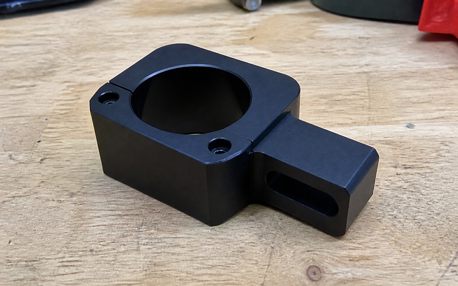
OEM machining parts are made to an equipment maker's controlled design for incorporation into its own products, service inventory, or production assemblies. A usable program connects the CAD model and drawing to revision control, material specification, inspection needs, packaging, and repeat-order requirements.
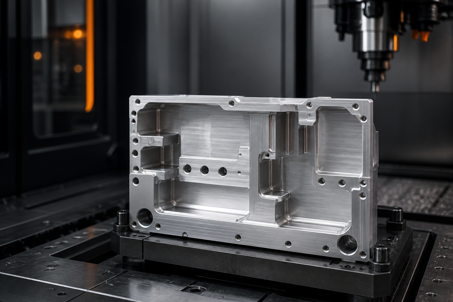
Core inputs
A good quote package contains a 3D model, drawing, revision, material grade, finish, quantity, functional tolerances, required documentation, and packaging or labeling instruction.
| Control point | What it prevents |
|---|---|
| Revision and interfaces | Manufacturing an obsolete or incomplete interpretation. |
| Material and finish | Unexpected performance, cosmetic, or assembly differences. |
| Acceptance method | Disagreement about what constitutes an acceptable part or kit. |
Repeat Build, Inspection, and Receiving
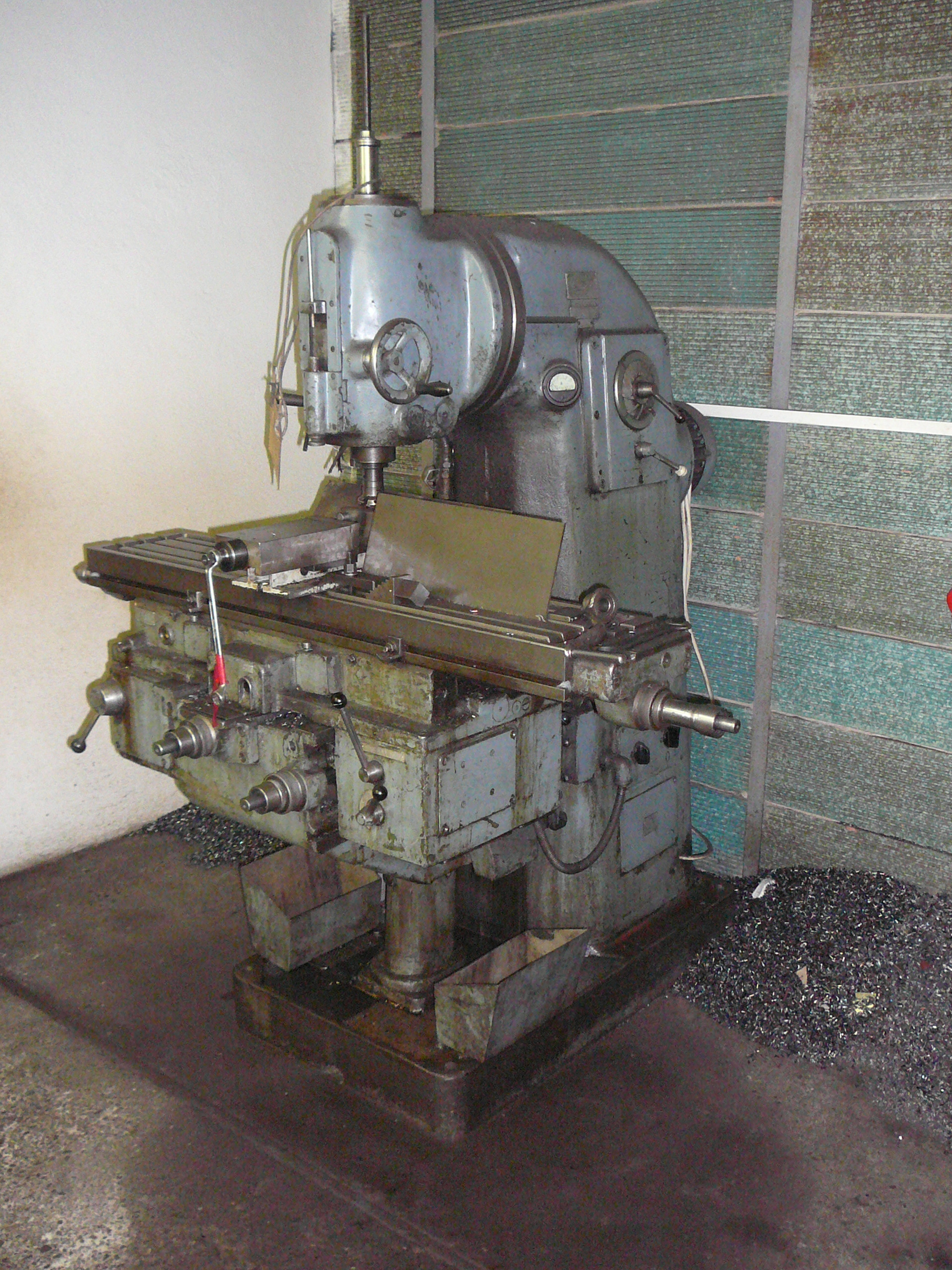
The workflow reviews technical files, locks the revision and bill of requirements, selects the manufacturing route, verifies the first article or critical dimensions, and maintains traceable production and packaging instructions for subsequent releases.
Part / assembly context
Key requirements include controlled prints, critical interfaces, material and finish, revision status, quantity, inspection documentation, marking, packaging, and clear change approval. OEM work commonly covers custom housings, brackets, shafts, fittings, machined plates, fluid components, hardware, and subcomponents that support an original product line.
Quality and packaging
Acceptance should focus on critical features and traceable revision control. Define first-article, in-process, or final-inspection expectations before release. Protect finished parts from handling and specify any identification, kit grouping, or service-spare packing required by the receiving organization.
Release note: A controlled drawing, revision process, and clear receiving criteria are more reliable than relying only on an informal sample or prior build.
Key Program Parameters
OEM machining is a manufacturing arrangement, not a single process. The list below describes the parameters most often set when a part enters the OEM program: revision control, sourcing, inspection, and repeat-order handling.
| Parameter | Typical Value |
|---|---|
| Drawing and model format | STEP, IGES, CATIA, NX, SolidWorks, plus PDF drawing with revision |
| Revision handling | Customer-controlled revision number, ECO, or change order referenced on each release |
| Dimensional tolerance | Per drawing, ISO 2768-m default where not specified, tight tolerance on request |
| Batch range | From a single first-article build to ongoing scheduled releases |
| Lead time | Quoted against the part, material, and release schedule; 2–6 weeks typical for a new program |
| Material sourcing | Customer-supplied, nominated distributor, or in-house stock with mill cert |
| Surface finish | As-machined, bead blast, anodize, powder coat, plating, passivation, or per drawing |
| Inspection documentation | First-article inspection report, in-process checks, final inspection, material cert on request |
| Traceability | Heat lot, batch, and serial number tracking where specified by the customer |
| Packaging and labeling | Per customer specification; kit grouping, part number, and revision on each package |
| NDA and quality agreement | Available on request for confidential designs and supply programs |
| Logistics | Single shipment, scheduled releases, kanban, or vendor-managed inventory as agreed |
Materials We Source and Machine
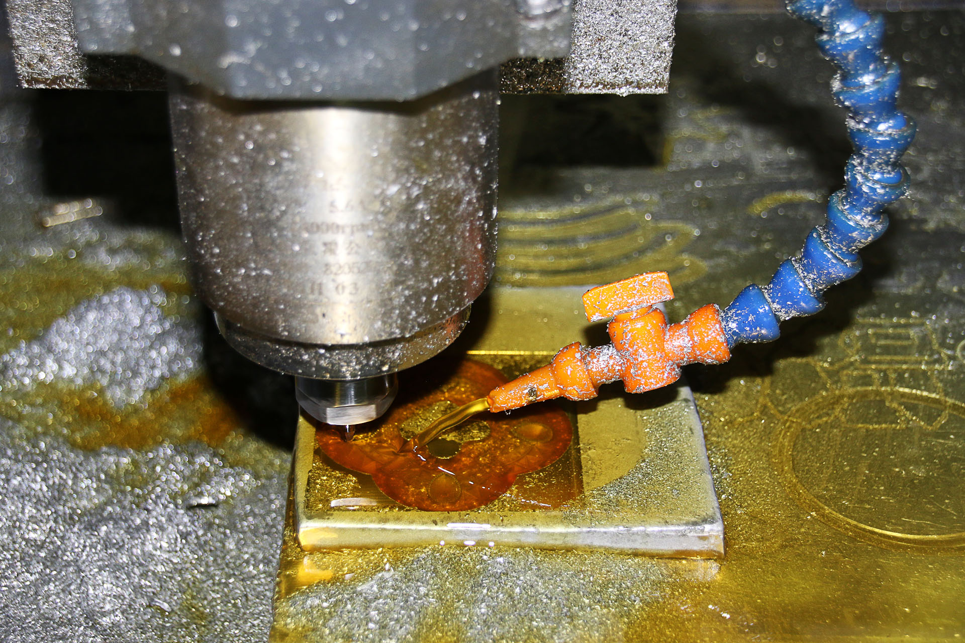
OEM programs typically use controlled grades with material certificates. The list below covers the families most often drawn into an OEM program; specific grades and suppliers follow the customer's specification.
- Carbon and alloy steel — 1018, 1045, 4140, 4340, A36, A572
- Stainless steel — 303, 304 / 304L, 316 / 316L, 321, 410, 17-4 PH
- Aluminum — 6061, 6063, 7075, 2024, 5052, MIC-6 tool plate
- Brass and copper — C360, C464 (naval brass), C110, C145
- Tool steel — A2, D2, O1, S7, H13, P20
- Engineering plastics — Delrin (POM-C / POM-H), UHMW-PE, Nylon 6/6, PEEK, PTFE
- Cast and molded items — machined from supplied castings, forgings, or molded blanks
- Bought-in hardware — fasteners, inserts, dowel pins per customer specification
Standard Tolerances & Achievable Precision
The tolerance on an OEM part is set by the drawing, not by the shop. Where the drawing is silent, the default below is applied and any functional dimension is reviewed during the DFM pass.
- Linear tolerance: ±0.1 mm standard, ±0.05 mm on request, ±0.025 mm for tight-tolerance features
- Hole tolerance: ±0.05 mm on standard features, ±0.025 mm on press-fit and dowel features
- Surface finish: Ra 1.6 µm standard as-machined, finer on request
- Flatness and parallelism: per drawing; 0.02 mm over 100 mm achievable on request
- ISO 2768-m used as default general tolerance on drawings that do not specify otherwise
- GD&T callouts (datums, profile, position) are honored and verified against the print
Surface Finish & Treatment Options
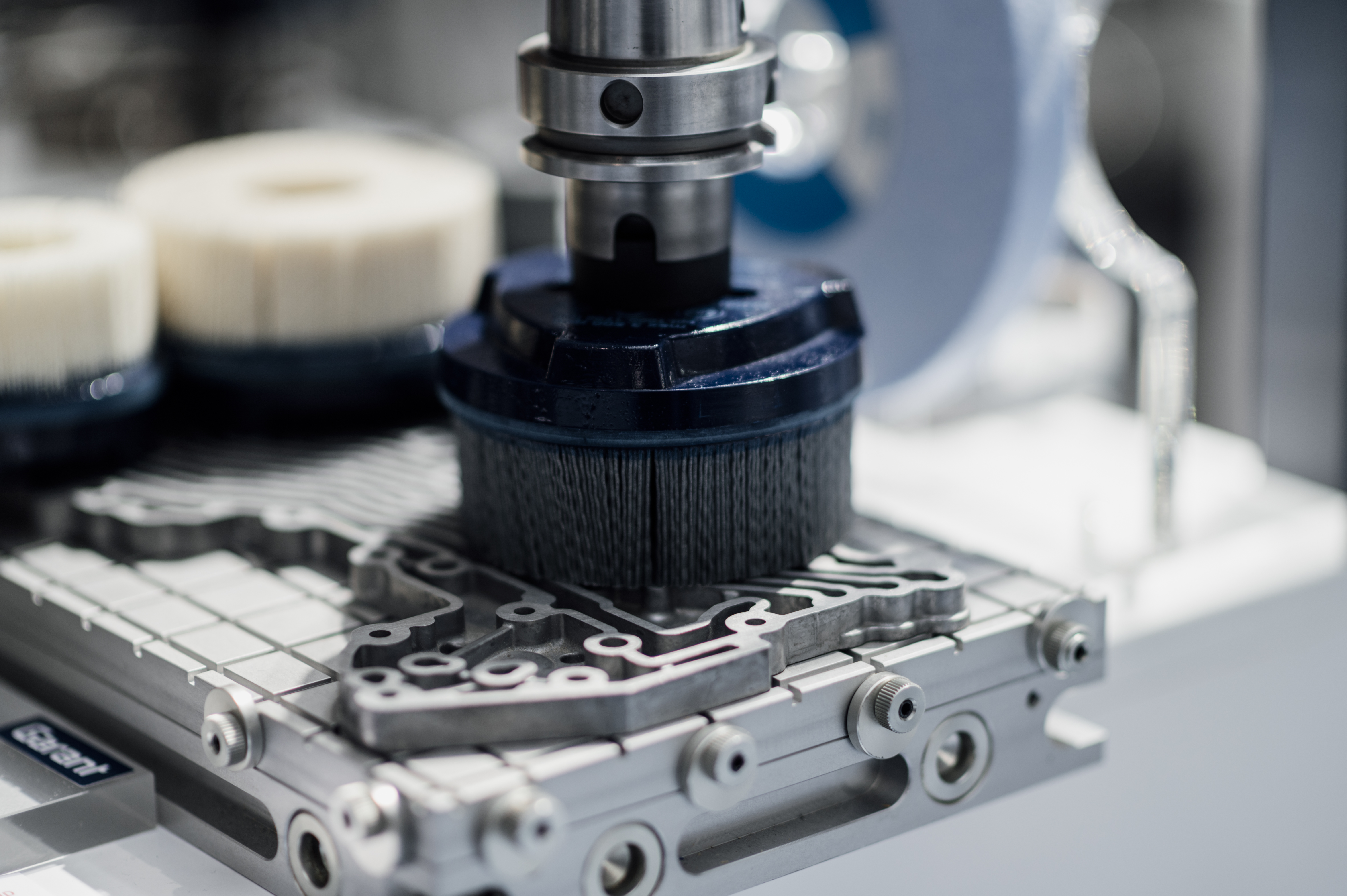
Surface finish is part of the OEM specification. The list below shows the finishes most often specified on OEM machined parts.
- As-machined (standard mill finish)
- Bead blast, shot blast, or tumble deburr for cosmetic uniformity
- Aluminum anodizing: Type II (decorative) and Type III (hard anodize)
- Powder coat over bead-blasted surface
- Wet paint or primer with color code per customer specification
- Electroplating: zinc, nickel, chrome, tin, gold, silver
- Electroless nickel plating (EN) for wear and corrosion resistance
- Passivation on stainless steel (ASTM A967 / AMS 2700)
- Black oxide or phosphate coating on steel
- Polishing, buffing, or mirror finish on cosmetic surfaces
- Laser marking, engraving, or silk-screen printing for identification
Quality Control & Documentation
OEM work is documented at every step so the customer can rebuild the part on a future release. Documentation level is matched to the program requirement.
- First-article inspection (FAI) report against the customer drawing and revision
- In-process dimensional checks at setup and during the run
- Final inspection report with dimensions, features, and acceptance criteria
- CMM inspection on complex geometry or tight-tolerance features
- Surface roughness measurement with a portable or bench roughness tester
- Hardness testing on tool steel, hardened, or heat-treated parts
- Material certificate (mill cert) and traceability to heat lot when specified
- PPAP, ISIR, or other customer-specific submission packages on request
- Non-conformance and deviation handling through a controlled process
- Calibrated inspection equipment traceable to national or international standards
Design Considerations (DFM Tips)
- Send the latest revision with the RFQ so the part is not quoted on an obsolete drawing
- Mark functional and cosmetic surfaces clearly so the inspection scope is unambiguous
- Avoid dual-tolerance stacks by calling out datums and primary references once
- Specify only the tolerances the function needs; tighter tolerance adds cost without value
- Group features by setup so the part can be machined in the fewest operations possible
- Allow a chamfer or radius on all sharp machined edges unless the drawing forbids it
- Indicate the surface finish on every face that matters, including threads and bores
- Call out thread spec, depth, and class so the tap drill and threading tool are correct
- Reference standard hardware (DIN, ISO, ANSI) rather than proprietary patterns where possible
- Plan a small first-article run before the production release to confirm fit and inspection
Industries & Applications
OEM machined parts enter the customer's product directly. The list below shows the industries and parts most often supported by our OEM program.
- Industrial machinery — housings, brackets, frames, gear blanks, custom shafts
- Automation and robotics — fixture plates, sensor mounts, end-of-arm components
- Automotive and off-highway — prototype and low-volume production components
- Aerospace and defense — ground-support tooling, brackets, ground equipment
- Medical and laboratory — equipment housings, instrument components, lab fixtures
- Electronics and semiconductor — chassis elements, sensor bodies, mounting plates
- Energy — power equipment components, electrical enclosure hardware
- Service and spare parts — replacement parts, legacy components, retrofit hardware
Frequently Asked Questions
What information is needed to start an OEM program?
A 3D model, the controlled drawing with revision number, the material specification, the surface finish, the quantity, the inspection scope, and the packaging or labeling requirement. An NDA can be signed before the model is shared if needed.
How is revision control handled on repeat orders?
Each release is quoted and built against the revision number provided with the order. Drawing changes are reviewed with the customer before the next release, and a first-article layout is generated whenever the revision changes.
Can the program include bought-in hardware and subassemblies?
Yes. Fasteners, inserts, bearings, and other bought-in items can be sourced to the customer's specification and delivered with the machined parts as a kitted or assembled unit.
What inspection documents are provided?
First-article inspection report, in-process checks, final inspection report, material certificates, and PPAP or ISIR packages where the customer program requires them.
How are repeat orders scheduled?
Repeat orders are scheduled as one-time releases, blanket orders with call-offs, kanban, or vendor-managed inventory. The schedule is reviewed at quote time and updated whenever the demand pattern changes.
Is a quality agreement or NDA available?
Yes. NDAs, quality agreements, and supplier qualification documents can be signed before sensitive designs and program information are exchanged.
How to Get a Quote
Send the 3D model (STEP preferred), the controlled drawing with revision, the material grade, the surface finish, the inspection level required, the expected annual quantity, the packaging and labeling specification, and any logistics or supply arrangement. The reply includes a DFM review, a lead time for first-article and production release, and a unit price. NDA, quality agreement, and supplier qualification documents are available on request.
Process Flow & Manufacturing Sequence
An OEM release is built around the controlled drawing and revision. The sequence below describes the operations from drawing receipt to packaged shipment, and is the working flow used on every OEM release.
- Drawing and model intake — receive the 3D model (STEP preferred), the controlled drawing with revision number, the BOM, and the customer specification; sign NDA where required before the model is opened.
- Revision and ECO check — confirm the drawing revision, the ECO, and any open deviation notes; record the revision against the part number in the program tracker.
- DFM and manufacturability review — review the model against the available processes, machine tools, and tooling; flag any feature that does not fit a process and propose a drawing-level change with the customer.
- Process plan and routing — select the machines, workholding, tooling, and setup sequence; identify any operation that requires a subcontract (heat-treat, plating, anodize, grinding, EDM, etc.) and reserve a slot in the queue.
- Material sourcing — order bar, plate, casting, forging, or molded blank to specification; request mill cert and confirm heat lot traceability for traceable grades.
- Programming and setup — write the CNC program, set up tooling, fixtures, and zero references; verify the program on the machine with a dry run or air cut when the part is new.
- First-article cut — cut the first part on the chosen machine, deburr, and move to inspection; the first article is held for layout and FAI sign-off before the run continues.
- FAI and sign-off — measure the first article against every dimension, GD&T callout, and surface-finish note on the controlled drawing; sign the FAI report and release the part to production.
- Production run — machine the rest of the batch with in-process checks at the agreed frequency; replace tooling at planned intervals; re-verify after any setup or program change.
- Subcontract operations — release parts to the agreed subcontractors (heat-treat, plating, anodize, passivation, etc.) with the work order, drawing, revision, and any process notes; receive parts back with certifications.
- Final inspection — full layout on a sample of the batch or on every part per the program requirement; record dimensions, surface finish, hardness, and any functional test.
- Packaging, labeling, and release — bag, kit, label with part number, revision, and quantity; prepare the inspection documents, C of C, MTC, FAI, and ship per the customer release schedule.
Material Property Reference
The table below lists typical material properties for the grades most often drawn into an OEM program. Values are industry references and are confirmed against the supplied mill certificate when one is provided.
| Material | Density (g/cm³) | Tensile Strength (MPa) | Yield Strength (MPa) | Hardness (HB) | Machinability Rating (%) |
|---|---|---|---|---|---|
| 1018 carbon steel | 7.87 | 440 | 370 | 131 | 70 |
| 1045 carbon steel | 7.85 | 565–655 | 310–450 | 163–197 | 55 |
| 4140 alloy steel | 7.85 | 655–1080 | 415–930 | 197–311 | 50 |
| Stainless 303 | 8.00 | 515–620 | 205–240 | 160–190 | 75 |
| Stainless 304 / 304L | 8.00 | 515–620 | 205–310 | 150–180 | 45 |
| Stainless 316 / 316L | 8.00 | 515–620 | 220–310 | 150–180 | 45 |
| 17-4 PH (H1025) | 7.78 | 1070 | 1000 | 311–352 | 35 |
| Aluminum 6061-T6 | 2.70 | 310 | 276 | 95 | 180 |
| Aluminum 7075-T6 | 2.81 | 572 | 503 | 150 | 150 |
| Brass C360 | 8.50 | 340–470 | 125–310 | 80–150 | 100 |
| Delrin POM-C | 1.41 | 69 | 65 | 120 (Rockwell M) | n/a (plastic) |
| PEEK (unfilled) | 1.30 | 100 | 90 | 99 (Rockwell M) | n/a (plastic) |
Cost Drivers & Lead Time Factors
OEM cost is driven by material grade and form, machine time (which itself depends on tolerance, surface finish, and feature complexity), workholding, tooling consumption, inspection scope, and any subcontracted operation. Lead time is driven by material availability, programming and tooling prep, subcontract queue, and the inspection and documentation cycle. The table below summarizes typical lead times by program type; an exact lead time is quoted against the part and the release schedule.
| Program Type | Typical Lead Time | Main Driver |
|---|---|---|
| First-article on stock material, no finish | 5–10 working days | Programming, tooling, FAI |
| First-article with heat-treat, plating, or anodize | 10–20 working days | Subcontractor queue and certifications |
| Low-volume production, 20–200 parts | 2–4 weeks | Material, machine time, and inspection |
| Annual program with scheduled releases | Per release plan, 1–6 weeks per call-off | Call-off volume, lot consolidation |
| PPAP or full submission package | 4–8 weeks | Documentation, layout, and customer approval |
| Repeat order with stored program | 3–10 working days | Material availability and capacity |
Common Defects & Prevention
OEM programs fail when the supply chain or the documentation drifts. The table below lists the most common OEM defects and the prevention step applied during the program.
| Defect | Cause | Prevention |
|---|---|---|
| Revision control issue | Drawing and model not aligned at release | Lock revision per release; FAI on every revision change |
| Traceability gap | Heat lot or batch not recorded on the traveler | Capture heat lot at receiving; record on every inspection report |
| Quality drift between batches | Tool wear, machine drift, or operator change | In-process checks at agreed frequency; replace tooling on schedule |
| BOM error (wrong part or hardware) | BOM revision older than the drawing revision | Generate BOM from the controlled 3D model; cross-check at FAI |
| Out-of-spec surface finish | Wrong feed, wrong tool, or wrong insert | Roughness check at FAI and in-process; lock tooling per feature |
| Cosmetic damage in transit | Packaging not specified or generic | Match packaging to the customer spec; foam, VCI, or crate as needed |
| Wrong material grade | Substitution without customer approval | Trace every bar to its MTC; raise deviation on any substitution |
| Heat-treat distortion | Stress relief not built into the process plan | Rough machine, stress relieve, finish machine; or finish after heat-treat |
Comparison With Related Processes
OEM machining is a program, not a single process. The table below compares an OEM CNC program to the alternative sourcing models that a customer often considers.
| Aspect | OEM Machining Program | Job-Shop Prototype | In-House Production |
|---|---|---|---|
| Revision and ECO control | Locked to customer release; FAI on every change | Per order; less formal change tracking | Internal; depends on customer's QMS |
| Traceability | Heat lot, batch, and traveler recorded | Material cert on request | Full, but at customer cost |
| Capacity | Scalable via multi-machine supplier | Limited per shop | Limited to customer's own fleet |
| Documentation | C of C, MTC, FAI, PPAP on request | Basic inspection report | Internal records |
| Repeat-order handling | Program stored; call-off schedule | Re-quoted each order | Per release plan |
| When to choose OEM program | Repeat part, controlled drawing, multiple releases | One-off prototype, no repeat | High-volume core process; capital already in place |
Industry Standards & Certifications
- ISO 9001:2015 — quality management system baseline
- AS9100D — aerospace QMS, applied to aerospace and defense OEM programs
- ISO 13485:2016 — medical device QMS, applied to medical and laboratory OEM parts
- IATF 16949 — automotive QMS, applied to automotive series production
- ISO 2768 (medium class) — default general tolerance on drawings that do not specify otherwise
- ASME Y14.5 — GD&T callouts honored on drawings that use the standard
- ISO 5459 — datum system reference for parts with complex datums
- RoHS and REACH — material compliance for electrical and consumer products
- ITAR — handling of parts subject to U.S. International Traffic in Arms Regulations, on request
- NADCAP — special process accreditation (heat-treat, coating, NDT) where the customer program calls for it
- EN 10204 3.1 / 3.2 — mill certificate type supplied with the material on request
Packaging, Shipping & Documentation
OEM packaging is matched to the customer specification and to the parts' cosmetic, corrosion, and ESD requirements. The list below describes the standard packaging options, the available shipping terms, and the documents that can be released with the shipment.
- Standard packaging — individual poly bag, foam or bubble wrap on cosmetic faces, VCI paper or oil for ferrous parts, ESD bag for sensitive components, partition or divider in a multi-part carton, wooden crate for export or heavy parts.
- Kit grouping — parts kitted by assembly in a single carton, each bag labeled with part number and revision; BOM and traveler included inside the master carton.
- Identification — outer label with part number, revision, quantity, supplier code, and ship-to address; bar code or QR label on request; serial number on individual parts where specified.
- Shipping options — parcel, LTL, full truckload, air freight, sea freight, customer-arranged carrier, and EXW / FOB / CIF / DDP terms; vendor-managed inventory and scheduled releases on long programs.
- Standard documents — packing list, commercial invoice, Certificate of Conformance (C of C), Mill Test Certificate (MTC), First-Article Inspection (FAI) report, and dimensional / layout report.
- Customer-specific documents — PPAP, ISIR, PSW, control plan, signed travelers, photos, and signed torque logs on request; documents can be emailed in advance of physical shipment.
Related Capabilities & Cross-Services
OEM programs often pair custom machining with adjacent capabilities so a part ships as a ready-to-install component, a subassembly, or a controlled kit. The list below shows the services most often combined with an OEM machining program.
- 5-axis CNC machining — complex geometry, single-setup features, and reduced tolerance stack-up
- CNC turning and mill-turn — rotational features, shafts, and fittings alongside prismatic machining
- Surface grinding and cylindrical grinding — tight-tolerance flatness, parallelism, and surface finish
- Heat treatment — through-hardening, case-hardening, precipitation hardening, stress relief, and annealing via qualified subcontractors
- Surface treatment — anodize (Type II / III), chem-film, powder coat, plating (zinc, nickel, electroless nickel, tin, chrome), passivation, black oxide, and phosphate
- Assembly components — kitting, subassembly, and full unit build with controlled BOM
- Reverse engineering — legacy part rebuild, obsolete-spares program, and design-for-manufacture improvements
- Non-standard automation parts — custom brackets, sensor mounts, and EOAT for the customer's own production lines
- Prototyping — pre-production prototypes and bridge production before the OEM release schedule starts
- Engineering support — DFM feedback, drawing redline proposals, material substitution, and supplier-managed inventory


