
Capture the Interface and Operating Context
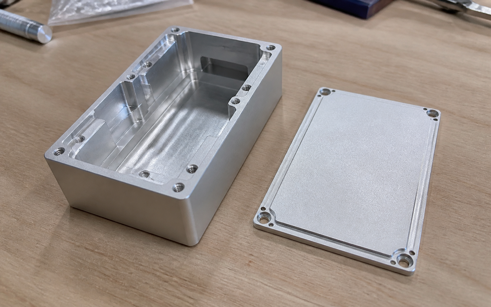
Non-standard automation parts are custom components made for a specific cell, fixture, machine, robot, sensor layout, or handling process. They are often neither catalog items nor generic machine parts, so their value lies in matching the intended interface, motion, load path, safety envelope, and maintenance approach.
Core inputs
Provide an assembly model, machine and robot interfaces, load or cycle information, desired adjustability, cable/air routing, safety constraints, material preference, surface treatment, and service-access needs.
| Control point | What it prevents |
|---|---|
| Revision and interfaces | Manufacturing an obsolete or incomplete interpretation. |
| Material and finish | Unexpected performance, cosmetic, or assembly differences. |
| Acceptance method | Disagreement about what constitutes an acceptable part or kit. |
Build for Fit-Up, Access, and Service
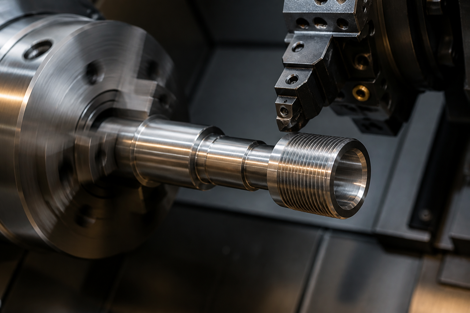
The workflow begins with the automation concept and interfaces, then translates critical dimensions and load requirements into controlled drawings. Machining, purchased hardware integration, inspection, and fit-up feedback are coordinated so the part works in the larger system.
Part / assembly context
Typical features include locating bores, sensor interfaces, robotic-tool mounting patterns, cable or pneumatic passages, slots for adjustment, guarded edges, jigs, clamps, custom brackets, and machine-frame adapters. Typical parts include end-of-arm tooling elements, fixture plates, nest blocks, sensor mounts, changeover parts, guides, custom guards, robot adapters, and automation subassembly components.
Quality and packaging
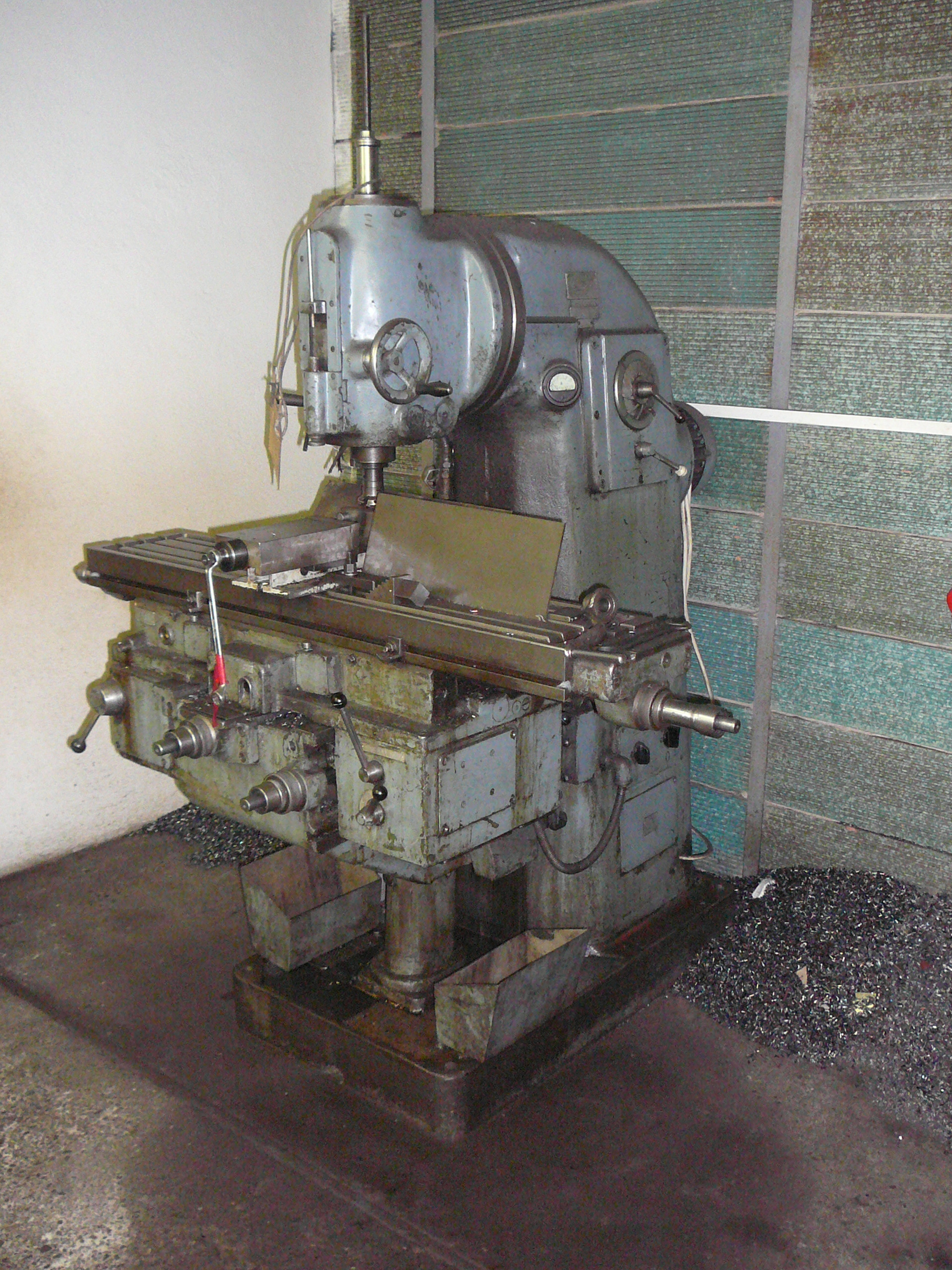
Inspection should verify the mounting pattern, locating datums, clearance features, critical hole positions, threads, interfaces with purchased items, and any safety-related geometry. Select finishes for wear, corrosion resistance, visibility, cleaning, and electrical needs. Protect functional bores, threads, and locating surfaces through any coating process.
Release note: A controlled drawing, revision process, and clear receiving criteria are more reliable than relying only on an informal sample or prior build.
Key Program Parameters
Non-standard automation parts are custom components built to match a specific cell, fixture, machine, robot, or sensor layout. The list below describes the parameters most often set at the start of a project.
| Parameter | Typical Value |
|---|---|
| Interface to existing system | Robot flange (ISO 9409-1), machine table, conveyor, sensor, pneumatic manifold, or custom |
| Mounting pattern | Per the mating component, dowel-pin located where repeatability matters |
| Operating load | Static and dynamic load defined by the cycle; reviewed against the part cross-section |
| Cycle rate | Quoted against the customer's cycle target; affects material, finish, and joint design |
| Locating tolerance | ±0.05 mm on dowel and locating features, ±0.1 mm on mounting pattern |
| Batch range | 1 prototype to low-volume production; repeat orders scheduled as the line evolves |
| Lead time | 2–6 weeks for first-article, faster on repeat parts with stored programs |
| Cable and air routing | Internal channels, cable ties, bulkhead fittings, or split clamps per the customer |
| Service access | Adjustment slots, access panels, removable hardware, and labeled service points |
| Safety-related geometry | Edge rounding, guarding features, clearance to motion, marked on the drawing |
| Inspection | FAI on the first article, layout against the mating component, and a fit-up report |
| File formats | STEP, IGES, native CAD, plus a 2D drawing with revision |
Typical Materials and Finishes
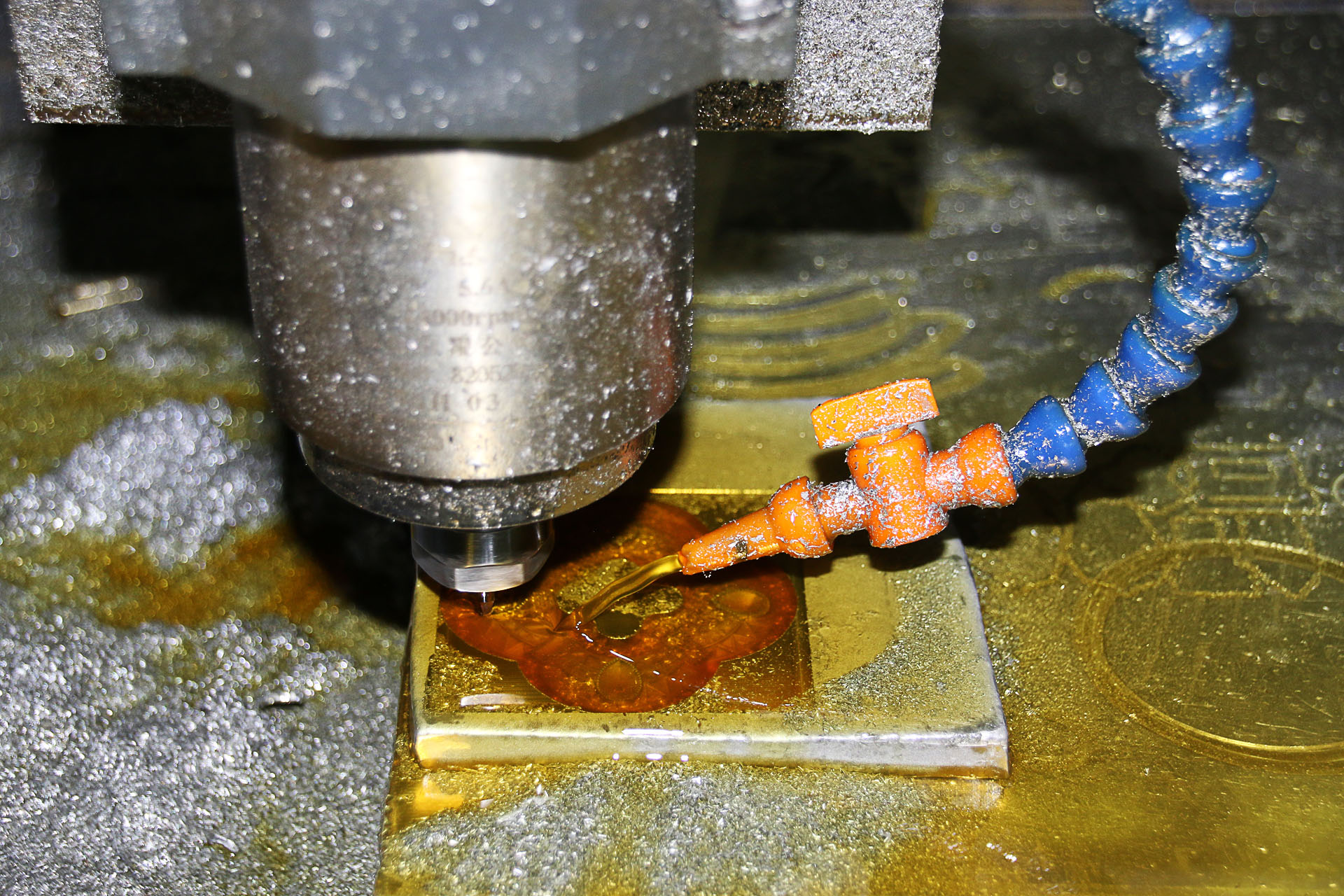
Material and finish are chosen against the load, the cycle, the environment, and the cosmetic requirement. The list below covers the options most often specified.
- Aluminum — 6061, 7075, 5052, MIC-6 for lightweight brackets, mounts, and panels
- Steel — 1018, 1045, A36 for frames, bases, and structural elements
- Hardened steel — 4140, 4340 pre-hard, A2, D2 for wear surfaces and tooling
- Stainless steel — 304 / 316 for food, pharma, and cleanroom environments
- Engineering plastics — Delrin, UHMW, Nylon, PEEK for wear pads, guides, and insulators
- Brass and copper — for electrical and grounding components
- Anodize (Type II / Type III) — aluminum cosmetic or wear surface
- Hard chrome, electroless nickel, or nitriding — wear and corrosion on steel parts
- Powder coat or wet paint — cosmetic color, branding, and environment protection
- Black oxide, zinc plating, or zinc flake — steel hardware and structural components
Standard Tolerances & Achievable Precision
Automation parts are usually matched to a mating component, so the tolerance is set against the interface, not the part alone. The list below is a working range; the actual tolerance is reviewed per feature.
- Locating features (dowel, register, pilot): ±0.025 mm to ±0.05 mm on the new part
- Mounting hole pattern: ±0.1 mm to ±0.05 mm depending on the fastener and dowel strategy
- Linear dimensions: ±0.05 mm standard, ±0.025 mm on request for tight-tolerance features
- Flatness and parallelism: 0.02 mm to 0.05 mm over 100 mm on request
- Threaded holes: per metric (6H) or unified (2B) class, depth and engagement per drawing
- Surface finish on locating surfaces: Ra 0.8 µm or better where repeatability matters
- ISO 2768-m used as default general tolerance on drawings that do not specify otherwise
Surface, Coating, and Service Finish
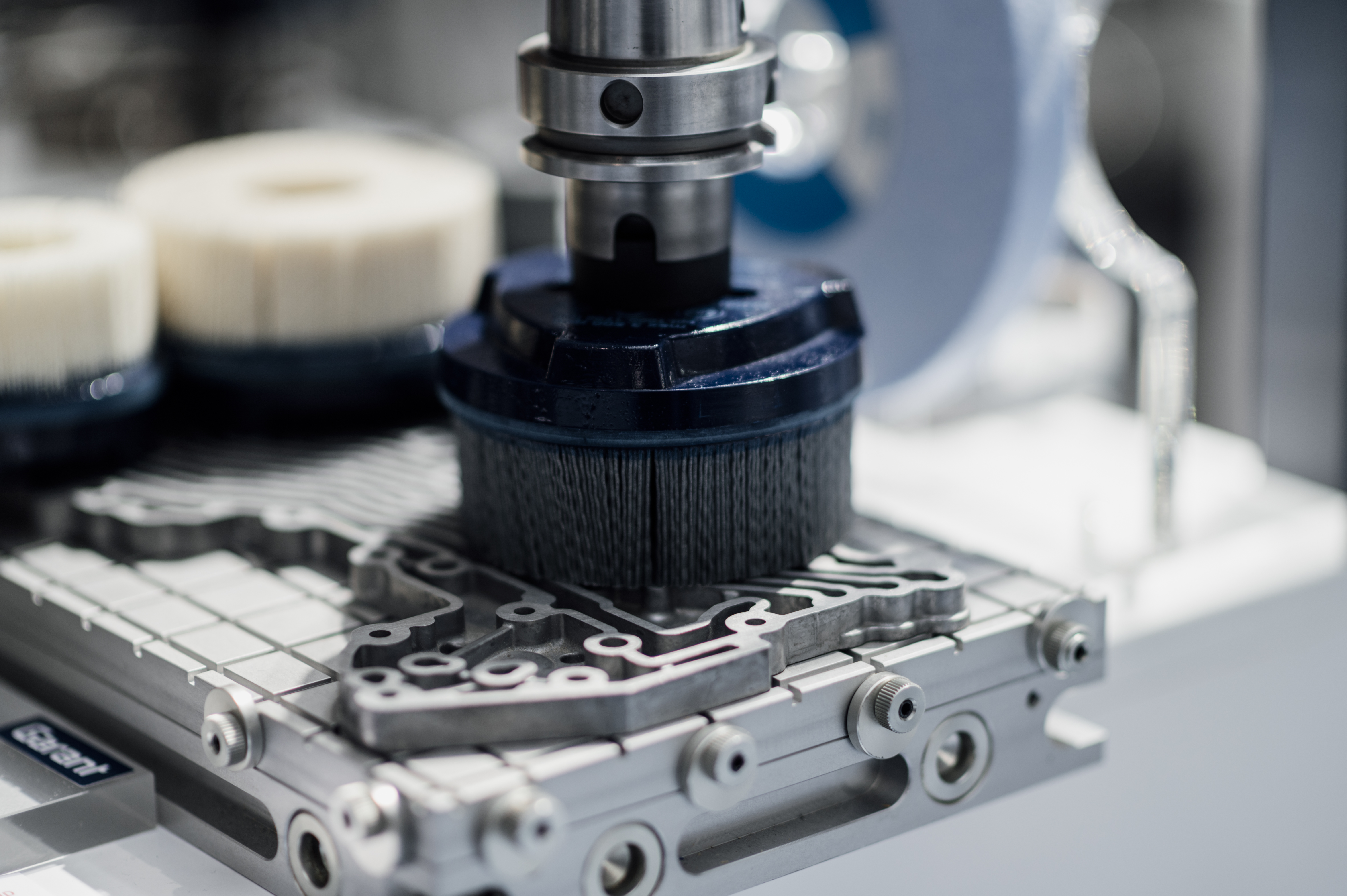
Surface finish is selected for wear, corrosion, visibility, and cleanability. The list below shows the finishes most often specified on automation parts.
- As-machined for hidden or non-cosmetic faces
- Bead blast or shot blast for cosmetic uniformity on visible parts
- Aluminum anodize (Type II decorative, Type III hard) for wear and color
- Powder coat or wet paint for color branding and environment protection
- Electroless nickel or hard chrome on wear surfaces
- Passivation on stainless steel parts after machining
- Black oxide or zinc plating on steel hardware and structural elements
- Anti-seize or dry-film lubricant on threads and locating surfaces
- Polished or electropolished surface for cleanroom or food-grade use
- Laser marking, engraving, or silk-screen for identification and brand
Quality Control & Inspection
The new part is checked against the customer drawing, the mating component, and the operating cycle. The list below covers the inspection points most often applied.
- First-article inspection against the drawing and revision
- Fit-up report or trial build against the mating component (robot, fixture, machine)
- CMM layout on complex geometry or tight-tolerance features
- Surface roughness check on locating and sealing surfaces
- Hardness test on hardened or heat-treated components
- Functional cycle test on the assembled cell where the part is safety- or motion-related
- Visual inspection of edges, threads, and cosmetic surfaces
- Marking, labeling, and packaging review against the customer specification
- Inspection report and traceable material cert on request
Design Considerations (DFM Tips)
- Send the assembly model and the mating component so the interface is reviewed, not just the part
- Mark load path, dowel, and locating surfaces clearly on the drawing
- Specify the robot or machine interface standard (for example ISO 9409-1) instead of redrawing the pattern
- Allow cable and air routing in the early concept so it is not forced into a small channel later
- Plan for service: keep fasteners accessible and label them where they are hidden in operation
- Round sharp edges that face the operator or a moving component, and note the radius on the print
- Avoid deep pockets and thin walls that add cost without adding function
- Use standard insert and fastener sizes to keep the BOM short and the service parts available
- Plan the adjustment slot or shim stack at the design stage, not after the part is built
- For high-cycle parts, plan a wear surface that can be replaced instead of scrapping the whole part
Industries & Applications
Non-standard automation parts are used wherever a standard catalog item does not fit the cell, the line, or the robot. The list below shows the industries and parts most often supported.
- Automotive manufacturing — welding jigs, fixture plates, end-of-arm tooling, transfer components
- Electronics and semiconductor — handler parts, test fixtures, magazine components, sensor brackets
- Medical device and pharma — cleanroom fixtures, filling and packaging components, stainless brackets
- Food and beverage — conveyor components, sanitary brackets, washdown-rated hardware
- Aerospace and defense — ground-support tooling, assembly fixtures, custom tool mounts
- General assembly — operator stations, light-curtain mounts, machine guarding, custom safety devices
- Robotics integration — EOAT elements, gripper fingers, changeover adapters, cable management
- Energy and power — cell fixtures for battery and solar production, custom test rigs
Frequently Asked Questions
What information is needed to start an automation-part project?
The assembly model, the mating component (robot, machine, sensor, fixture), the operating load and cycle, the cable or air routing, the safety and service requirements, the material and finish, and the target quantity.
Can the part be built to a standard robot or machine interface?
Yes. Common robot flanges (ISO 9409-1, including 31.5, 40, 50, 63, 80, 100, 125, 160, 200), machine tables, and sensor mounts are referenced directly so the part matches the existing component without re-engineering the pattern.
How is fit-up handled before the part is released?
A first-article build is checked against the mating component on the bench or in the cell. Any interface issue is corrected on the model and drawing before the production run is started. A fit-up report is included where the customer needs it.
What about safety-related geometry on the part?
Edges, clearances, and guarding features are marked on the drawing. Sharp edges that face the operator or a moving component are rounded. The drawing should call out any feature that has a safety role so the inspection scope is clear.
Can a small batch of one-off parts be produced?
Yes. Non-standard automation work usually starts with a single part or a small batch, with the option of repeat releases as the line evolves. Programs are stored so repeat orders are quoted and built quickly.
Will the part be tested in the cell before sign-off?
Where the customer requests it, the part is built, fit-checked, and cycled in the cell by the customer's team or jointly. The result is documented in a fit-up report that becomes part of the project record.
How to Get a Quote
Send the assembly model, the mating component reference (robot, fixture, sensor, or machine), the operating load and cycle, the cable and air routing, the safety and service requirements, the material and finish preference, and the target quantity. The reply includes a DFM review of the interface and load path, a lead time for first-article and production release, and a unit price. Fit-up and in-cell test are quoted on request.
Process Flow & Manufacturing Sequence
A non-standard automation part is built to match a specific cell, fixture, machine, robot, or sensor layout. The sequence below describes the operations from interface and cycle review to packaged shipment, and is the working flow used on every automation-part project.
- Interface and cycle review — receive the assembly model, the mating component (robot, fixture, sensor, machine), the operating load, the cycle rate, the cable and air routing, and any safety or service requirement; sign NDA where required.
- Concept and load path — confirm the load path through the part, the locating scheme (dowel, register, pilot), the adjustment or shim plan, and any safety-related geometry that has to appear on the drawing.
- DFM and manufacturability — review the model for machinability, workholding, tooling access, and any feature that does not fit a process; flag changes with the customer before programming.
- Material and finish selection — confirm material grade and finish against the load, the cycle, the environment, and any cosmetic requirement; lock the heat-treat, coating, or plating step into the routing.
- Programming and fixture — write the CNC program, design or select a fixture, and plan the workholding so the part can be cut in the fewest setups.
- First-article cut — cut the first article on the chosen machine, deburr, and move to inspection; hold the part for FAI and fit-up against the mating component.
- FAI and drawing sign-off — measure the first article against the drawing and revision; sign the FAI report and release the part to the production run.
- Fit-up and in-cell test — where the customer requests it, install the part on the robot, fixture, machine, or sensor and run a cycle or function test; record any adjustment value used and update the traveler.
- Production run — machine the rest of the batch with in-process checks at the agreed frequency; replace tooling on schedule; re-verify the FAI on any setup or program change.
- Subcontract operations — release parts to the agreed subcontractors (heat-treat, anodize, hard chrome, plating) with the work order, drawing, revision, and process notes; receive parts back with certifications.
- Final inspection — full layout on a sample or on every part per the program requirement; record dimensions, surface finish, hardness, and any functional test result.
- Marking, packaging, and release — apply serial number, part number, revision, or barcode; pack with foam, VCI, or ESD protection; release with the inspection documents, C of C, MTC, and FAI.
Material Property Reference
The table below lists typical material properties for the materials most often specified on non-standard automation parts. Values are industry references and are confirmed against the supplied mill certificate when one is provided.
| Material | Density (g/cm³) | Tensile Strength (MPa) | Yield Strength (MPa) | Hardness (HB) | Machinability Rating (%) |
|---|---|---|---|---|---|
| Aluminum 6061-T6 | 2.70 | 310 | 276 | 95 | 180 |
| Aluminum 7075-T6 | 2.81 | 572 | 503 | 150 | 150 |
| Aluminum 5052 | 2.68 | 210–260 | 130–193 | 60–75 | 200 |
| MIC-6 aluminum tool plate | 2.70 | 165 | 140 | 65 | 190 |
| 1018 carbon steel | 7.87 | 440 | 370 | 131 | 70 |
| A36 structural steel | 7.85 | 400–550 | 250 | 119–159 | 70 |
| 4140 pre-hard (28–32 HRC) | 7.85 | 930–1080 | 760–930 | 280–320 | 50 |
| A2 tool steel (annealed) | 7.86 | 700 | 540 | 200–235 | 35 |
| Stainless 304 / 304L | 8.00 | 515–620 | 205–310 | 150–180 | 45 |
| Stainless 316 / 316L | 8.00 | 515–620 | 220–310 | 150–180 | 45 |
| Delrin POM-C | 1.41 | 69 | 65 | 120 (Rockwell M) | n/a (plastic) |
| PEEK (unfilled) | 1.30 | 100 | 90 | 99 (Rockwell M) | n/a (plastic) |
Cost Drivers & Lead Time Factors
Automation-part cost is driven by material grade, machining time (which depends on tolerance, surface finish, and the number of setups), workholding and fixturing, tooling consumption, fit-up time, and any in-cell test. Lead time is driven by interface review, programming and fixture build, material availability, subcontract queue, and the fit-up cycle. The table below summarizes typical lead times by project type; an exact lead time is quoted against the part and the cell.
| Project Type | Typical Lead Time | Main Driver |
|---|---|---|
| First-article bracket or adapter, no finish | 1–2 weeks | Programming, tooling, FAI |
| EOAT element with anodize or hard coat | 2–3 weeks | Anodize queue and FAI |
| Fixture plate or nest block, multi-feature | 2–4 weeks | Machine time and inspection scope |
| Cell component with heat-treat, plating, or hard chrome | 3–5 weeks | Subcontractor queue and certifications |
| Component with in-cell fit-up and cycle test | 3–6 weeks | Cell access and customer schedule |
| Repeat order with stored program and fixture | 5–10 working days | Material availability and capacity |
Common Defects & Prevention
Non-standard automation parts fail when the interface, the load path, or the safety envelope is not designed in from the start. The table below lists the most common defects and the prevention step applied during the project.
| Defect | Cause | Prevention |
|---|---|---|
| Interface mismatch with mating component | Pattern copied from old drawing, not from the actual mating part | Reference the standard (ISO 9409-1) or measure the mating part |
| Load path unclear | Operating load not defined or not reviewed against cross-section | Mark load path on the drawing; check section at peak load |
| Safety envelope not designed in | Sharp edges and clearances not called out on the drawing | Round operator-facing edges; mark safety-related geometry |
| Cable / air routing forced into small channel | Routing not planned in the concept; added late in the build | Plan routing at the concept; reserve bend radius and clearance |
| Service access lost after build | Fastener location or part geometry blocks maintenance tools | Plan service before locking geometry; mark service points on the print |
| Repeatability drift in production | Dowel or locating surface out of tolerance | Hold ±0.025–0.05 mm on locating features; verify on FAI |
| Wear on a non-replaceable surface | Wear surface integrated into the main part | Make wear surfaces replaceable inserts where the cycle is high |
| Cosmetic damage on visible part | Handling or packaging not matched to the cosmetic spec | Use protective film, foam, and dedicated packaging for visible parts |
Comparison With Related Processes
A non-standard automation part sits between a custom machined part and a fully designed-and-built automation sub-system. The table below compares it to the alternative sourcing models a customer often considers.
| Aspect | Non-Standard Automation Part | Catalog / Standard Part | In-House Design & Build |
|---|---|---|---|
| Fit to existing cell | Designed to the cell, fixture, or robot | May require adapter or rework | Designed in-house from scratch |
| Lead time | 2–6 weeks for first article | Days to weeks from stock | Driven by internal engineering capacity |
| Engineering effort at customer | Low — supplier does the DFM | Low — part is standard | High — full design and build |
| Cost per part | Higher than catalog, lower than full re-design | Lowest per part, with adapter cost | Highest total cost |
| Best for | Existing cell with a specific gap | Common interfaces and standard loads | New cell, novel process, IP-sensitive design |
| When to choose non-standard automation part | Standard part does not fit, full re-design is too much | Interface and load match the catalog | Process is novel, IP must stay in-house |
Industry Standards & Certifications
- ISO 9001:2015 — quality management system baseline
- AS9100D — aerospace QMS, applied to aerospace and defense automation projects
- ISO 13485:2016 — medical device QMS, applied to medical and pharmaceutical automation
- IATF 16949 — automotive QMS, applied to automotive body and assembly automation
- ISO 9409-1 — robot mounting flange interface, referenced directly on robot-mounted parts
- ISO 13849 — safety of machinery, safety-related parts of control systems
- IEC 61508 / IEC 61511 — functional safety, applied where the part is part of a safety instrumented function
- ISO 4413 / ISO 4414 — hydraulic and pneumatic system safety, applied to fluid-power automation
- ANSI/RIA R15.06 / ISO 10218 — industrial robot safety, applied to robot cells and EOAT
- ISO 2768 (medium class) — default general tolerance on drawings that do not specify otherwise
- ASME Y14.5 — GD&T callouts honored on drawings that use the standard
- ISO 5459 — datum system reference for parts with complex datums
- RoHS and REACH — material compliance for electrical and consumer products
Packaging, Shipping & Documentation
Automation parts are packaged to protect the locating and cosmetic surfaces and to keep the part identifiable through fit-up. The list below describes the standard packaging, the available shipping options, and the documents that can be released with the shipment.
- Standard packaging — foam, bubble wrap, or VCI paper on locating and cosmetic surfaces; custom foam insert for repeat orders; individual bag with part number and revision label.
- Identification — outer label with part number, revision, quantity, and ship-to address; bar code, QR label, or serial number on request; orientation marks on the package where the part is asymmetric.
- Shipping options — parcel, LTL, full truckload, air freight, customer-arranged carrier, and EXW / FOB / CIF / DDP terms; line-side delivery to the cell on long programs.
- Standard documents — packing list, commercial invoice, Certificate of Conformance (C of C), First-Article Inspection (FAI) report, Mill Test Certificate (MTC), and dimensional / layout report.
- Supplementary documents — fit-up report against the mating component, cycle-test record, in-cell test results, and a service-points drawing where the part has safety or maintenance features.
Related Capabilities & Cross-Services
Non-standard automation parts are usually one element in a larger cell or line. The capabilities below are typically paired with the part to take it from a 3D model to a working, maintainable component in the cell.
- 5-axis CNC machining — complex interfaces, single-setup features, and reduced tolerance stack-up on robot and fixture parts
- CNC turning and mill-turn — bushings, pins, and rotational features for the assembly
- Surface and cylindrical grinding — tight-tolerance flatness, parallelism, and finish on locating and seal surfaces
- Heat treatment — through-hardening, case-hardening, nitriding, and stress relief on wear and structural parts
- Surface treatment — anodize (Type II / Type III), electroless nickel, hard chrome, chem-film, powder coat, passivation, and zinc plating
- Assembly components — kitting and subassembly of the part with hardware, fasteners, and bought-in items
- OEM machining program — revision-controlled, repeat-order supply of the part as the line evolves
- Reverse engineering — rebuild of legacy fixtures, brackets, and EOAT elements for which no controlled drawing exists
- Prototype machining — pre-production prototypes and bridge production before the line is live
- Engineering support — DFM feedback, drawing redline proposals, material substitution, and standardization of interfaces across the line


