
What the Process Does
Tapping and reaming are precision hole-finishing operations that serve different functional needs. Tapping cuts an internal thread so that a hole can accept a screw or fastener. Reaming takes a pre-drilled undersize hole to a controlled final diameter, improving its suitability for pins, dowels, close-fit shafts, and accurate assembly locations.
Process Flow
The machining sequence should be planned around the part's functional datums, feature access, material behavior, and the required inspection method. The detailed route is ultimately governed by the actual machine configuration, workholding, tool availability, and production quantity.
|
Process Stage |
Purpose |
|
1. Input review |
Confirm the 3D model, drawing, material, critical dimensions, datums, quantity, and finish requirements. |
|
2. Setup plan |
Select workholding, datum strategy, cutting tools, machining order, and access to all functional features. |
|
3. Machining |
The process starts with a correctly sized prepared hole. For tapping, the program synchronizes spindle rotation and feed to create the specified thread. For reaming, the hole is drilled undersize and then finished with a reamer to reach the final diameter. The order of operations, material, hole depth, and whether the hole is through or blind affect the final method. |
|
4. Verification |
Thread inspection can use go/no-go gauges or other specified methods. Reamed holes may be inspected for diameter, location, depth, roundness, and suitability for the intended close-fit component. Burrs at both sides of the hole must also be controlled. |
Design Intent
Clearly indicate whether the thread is metric or inch, right- or left-hand, through or blind, and whether a countersink or chamfer is required. For reamed holes, identify the required fit and the mating pin, shaft, or bushing where possible.
|
ENGINEERING INPUT Provide a 3D CAD model, a drawing with critical tolerances and datums, the material grade, requested quantity, surface finish, and any inspection or packaging requirements. |
Part Geometry and Materials
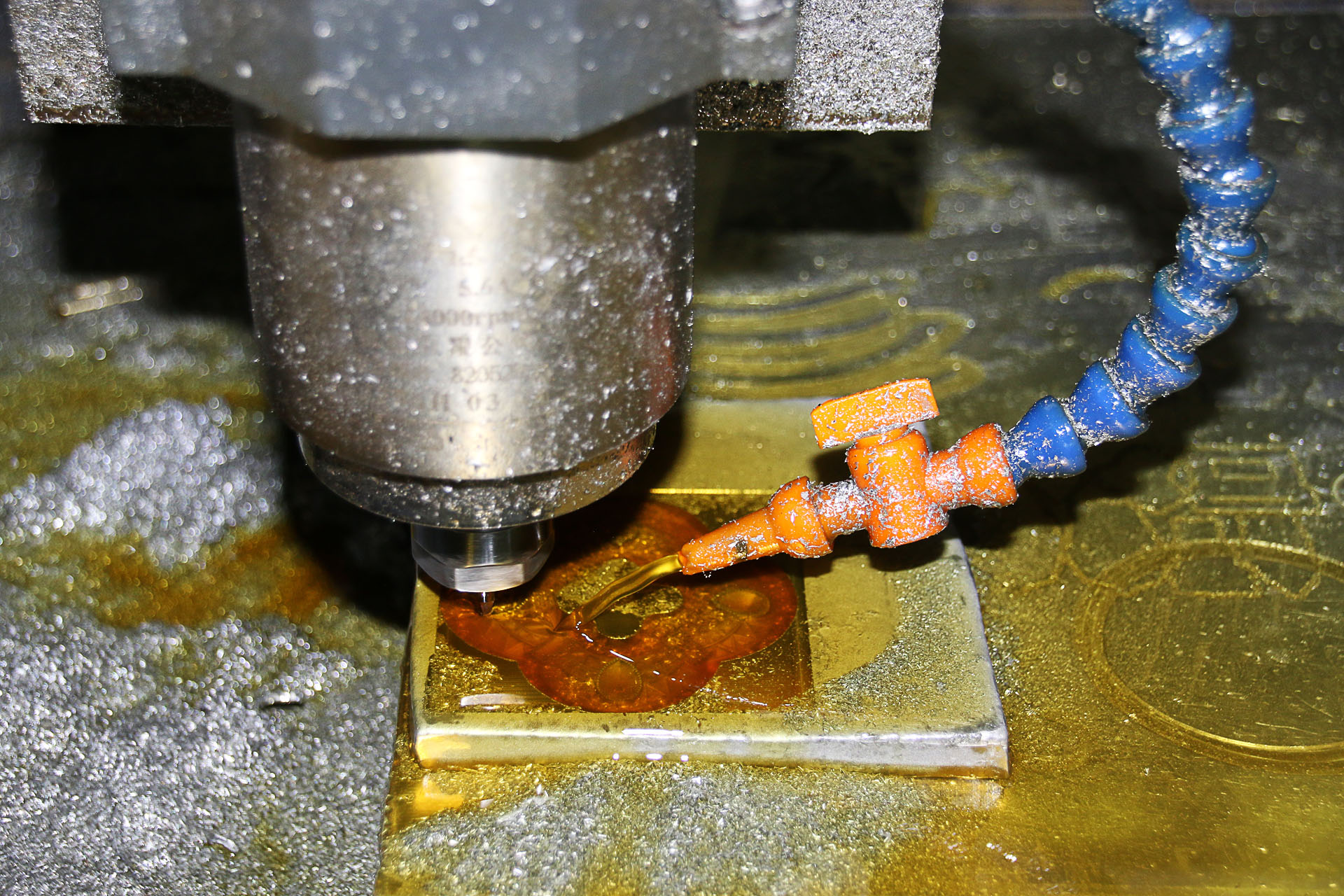
Features and Typical Components
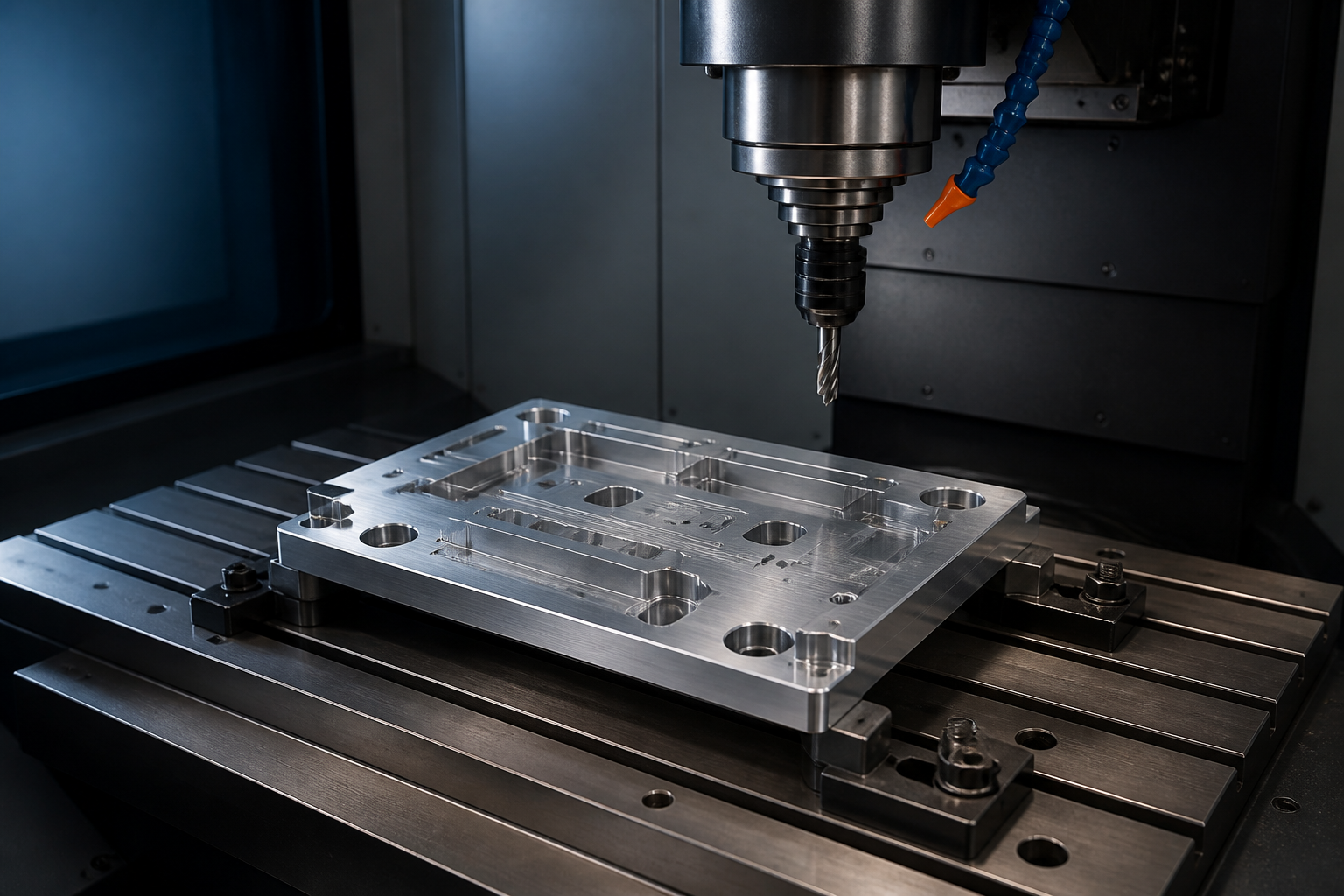
Key requirements include thread standard, size, pitch, class, depth, relief, bottom condition, and engagement length for tapped holes; and final diameter, tolerance, depth, positional requirement, and mating-part relationship for reamed holes.
Typical components Typical applications include mounting plates, brackets, tooling, enclosures, fixtures, valve bodies, equipment housings, jigs, sensor mounts, precision assemblies, and components using dowel-pin locations.
Material Selection
Aluminum, steel, stainless steel, brass, copper, titanium, and engineering plastics can all require threaded or reamed holes. Tool type and cutting conditions must be matched to the material, particularly when dealing with hard, abrasive, or stringy chips.
|
Material group |
What to consider |
Typical reason for selection |
|
Aluminum |
Machinability, thermal movement, cosmetic finish. |
Lightweight housings, brackets, fixtures, heat-management parts. |
|
Steel & stainless |
Strength, corrosion resistance, heat, chip control. |
Industrial, structural, fluid-system, precision mechanical parts. |
|
Brass, copper & titanium |
Conductivity, corrosion, strength-to-weight, cost. |
Fittings, electrical parts, high-performance or specialized components. |
|
Engineering plastics |
Stiffness, temperature, chemical environment, burr control. |
Insulating, lightweight, prototype, wear or fluid-contact parts. |
|
MATERIAL NOTE The material must be selected against functional needs first. Machinability, heat, corrosion, weight, cost, and the desired surface treatment should then be reviewed together. |
Technical Planning and Quality
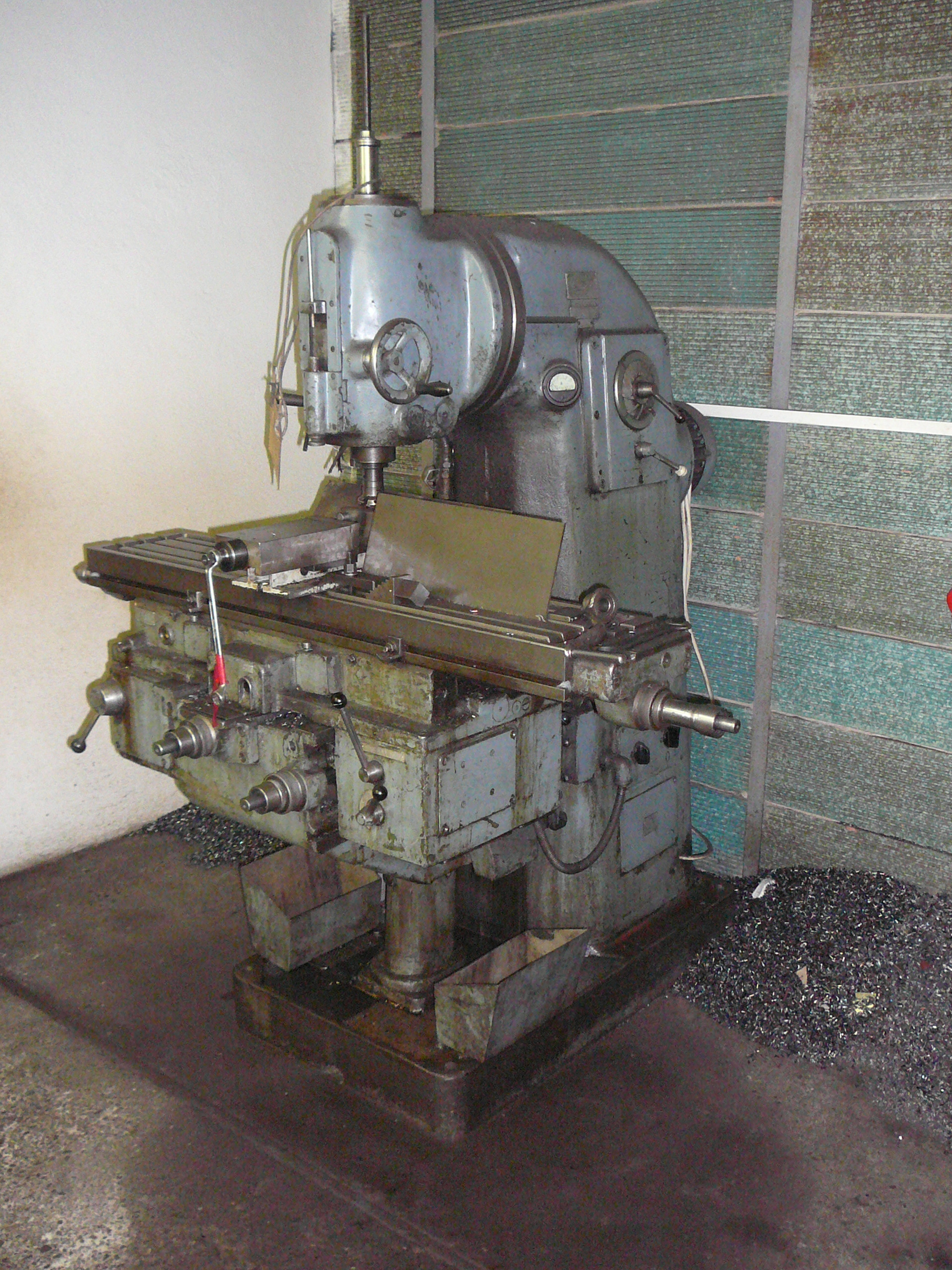
Manufacturing Considerations
Clearly indicate whether the thread is metric or inch, right- or left-hand, through or blind, and whether a countersink or chamfer is required. For reamed holes, identify the required fit and the mating pin, shaft, or bushing where possible.
Quality and Inspection
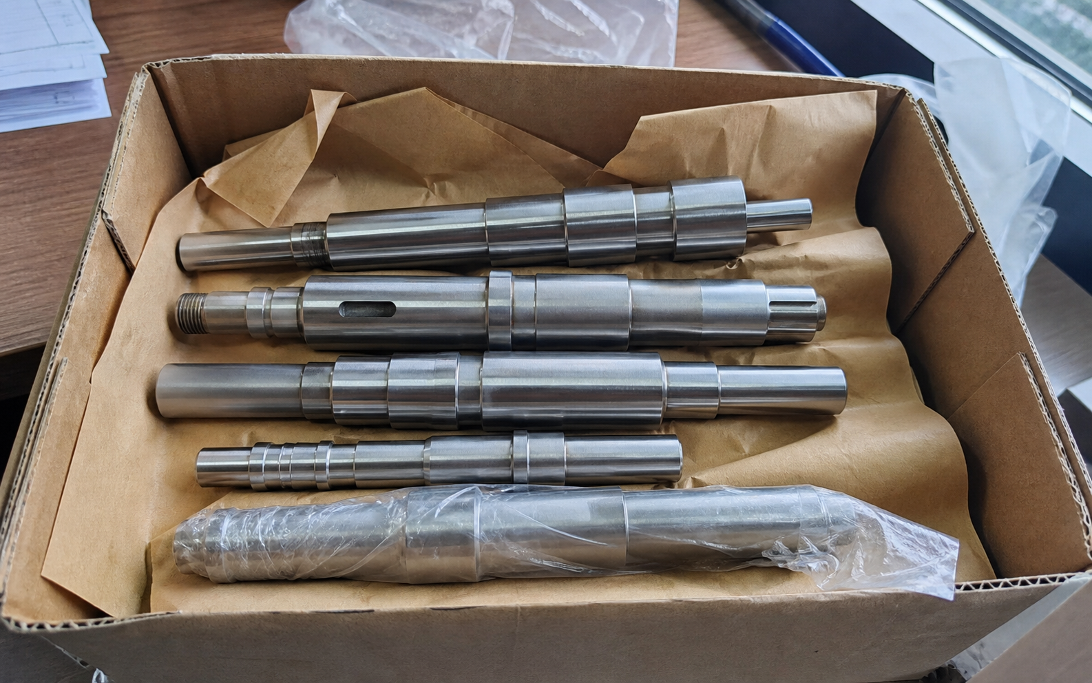
Thread inspection can use go/no-go gauges or other specified methods. Reamed holes may be inspected for diameter, location, depth, roundness, and suitability for the intended close-fit component. Burrs at both sides of the hole must also be controlled.
Surface Finish and Part Protection
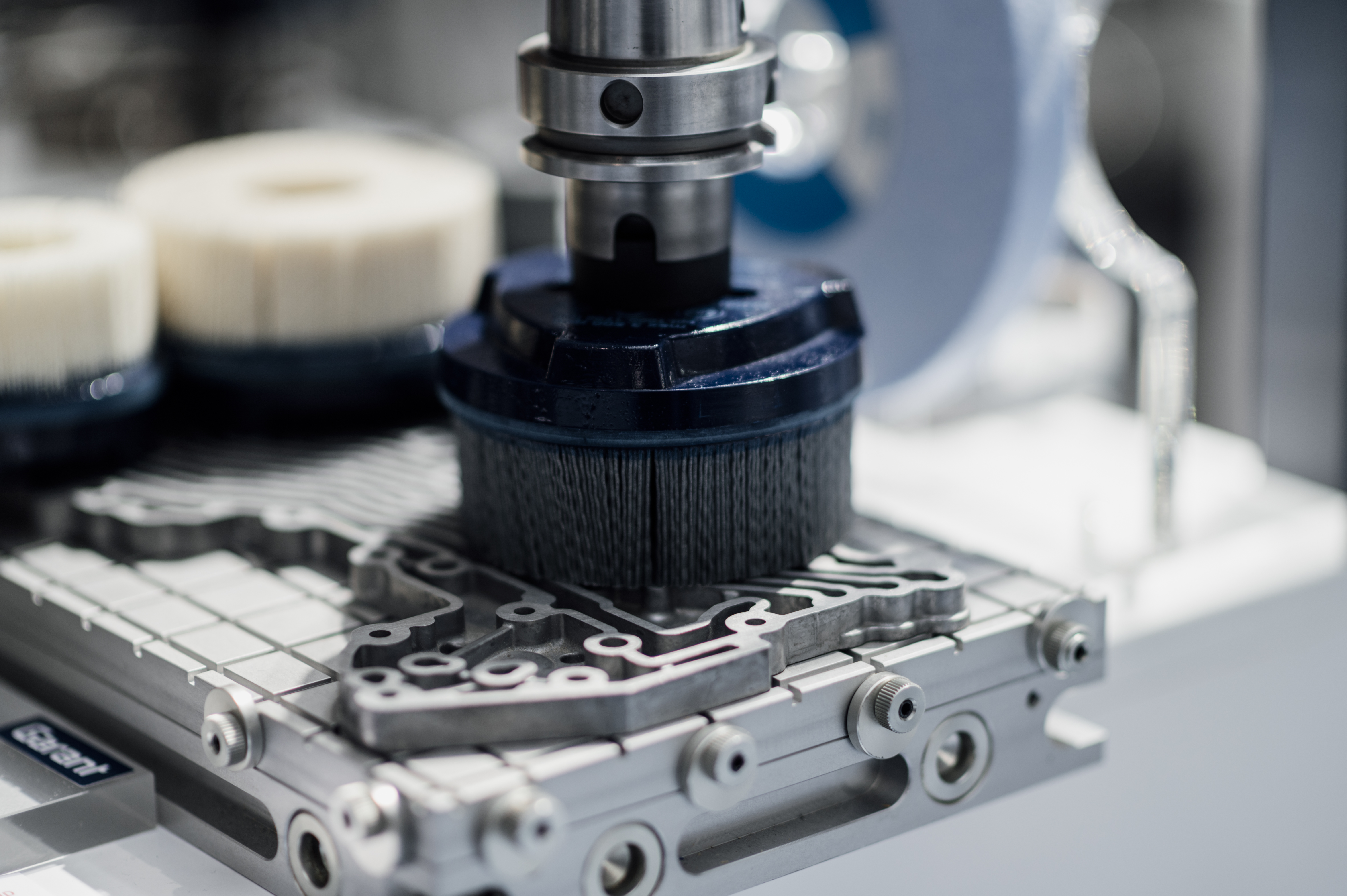
Finishing is usually secondary to functional integrity. If coating, anodizing, plating, or painting is specified, determine whether threads and close-fit holes need masking or post-finish sizing.
Before Production
A manufacturability review should confirm that the tolerance scheme is functional, the specified material is available, the workholding leaves access to critical faces, and the measurement plan can verify all requirements without ambiguity. Where an assembly interface is critical, provide the mating-part information or fit requirement.
|
DRAWING PRACTICE Call out the dimensions that matter to function. Avoid applying an unnecessarily tight general tolerance where only a limited number of features control the fit, motion, sealing, or alignment of the final assembly. |
Advantages and Applications
Why Select This Process
These operations make a machined part ready for assembly. Tapping supports reliable fastening, while reaming provides a controlled interface for accurate positioning and repeatable location.
Application Context
Product assemblies, automation equipment, fixtures, electronics housings, medical equipment, industrial machinery, robotics, automotive parts, and aerospace hardware commonly use tapped or reamed holes.
|
Application family |
Where the process adds value |
|
Prototype and product development |
Useful where a functional part, review sample, or process route must be validated before a larger production decision. |
|
Industrial and automation equipment |
Supports durable custom hardware, fixtures, housings, interfaces, shafts, passages, and assembly features. |
|
Precision and regulated equipment |
Supports geometry that must be documented through clear datums, material specifications, inspection requirements, and controlled finishing. |
When to Choose Another Process
Use tapping for an internal fastening thread and reaming for a precision plain hole. Where both functions are needed, they are normally separate features with their own preparation, tolerance, and inspection requirements.
|
QUOTE CHECKLIST Include model and drawing files, material grade, order quantity, material certification needs, finishing requirements, critical features, and target delivery date with the RFQ. |
Key Process Parameters
| Parameter | Typical Value |
|---|---|
| Tapping range, metric | M1.6 to M30 standard; M36 and above quoted on application |
| Tapping range, inch | #0-80 to 1"-8 UNC / UNF standard |
| Thread standards | ISO 261 / 262, ASME B1.1, BSP, NPT, NPTF, BSW / BSF, trapezoidal on request |
| Thread class (metric) | 6H internal standard; 4H5H, 5H, 6G, 6HX available |
| Thread class (inch) | 2B internal standard; 1B, 3B available |
| Maximum thread depth | Up to 3 × Ø in standard blind holes; deeper threads quoted per part |
| Reaming diameter range | Ø1.0 mm to Ø50 mm standard; larger sizes on request |
| Reaming tolerance | ±0.013 mm precision; ±0.025 mm standard |
| Reamed surface finish | Ra 0.4–1.6 µm typical, depending on material and tool |
| Reaming roundness | 0.005–0.015 mm |
| Tooling | Spiral-point, spiral-flute, and forming taps; carbide and HSS reamers; thread mills for large sizes |
| Batch range | Single-piece prototypes through 10,000-piece production runs |
| Typical lead time | 5–10 working days prototypes; 10–20 working days production |
| Accepted CAD formats | STEP, IGES, X_T, Parasolid, native SolidWorks / CATIA / NX / Fusion 360 |
Materials We Machine
- Aluminum alloys — 6061-T6, 7075-T6, 2024-T3, 6082, 5052, MIC-6
- Carbon and alloy steels — 1018, 1045, A36; 4140, 4340 pre-hard or Q&T to HRC 28–32
- Stainless steels — 303, 304 / 304L, 316 / 316L, 321, 410, 17-4PH, 15-5PH
- Tool and bearing steels — A2, D2, O1, S7, 52100
- Brass, bronze, and copper — C360 brass, C110 copper, C932 / C954 bronze (free-cutting grades for high-speed tapping)
- Cast iron and ductile iron — gray iron GG25, ductile iron 60-40-18
- Titanium — Grade 2, Grade 5 (Ti-6Al-4V)
- Engineering plastics — POM (Delrin), PEEK, PTFE, nylon, polycarbonate, HDPE
Standard Tolerances & Achievable Precision
Tapping and reaming are finishing operations. The starting hole is the foundation: a correct drill size, plus the right tool, coolant, and synchronised feed, controls the final thread and the final diameter.
- Tap thread class: ISO 6H / ASME 2B standard; tighter (5H, 4H5H, 1B) on request
- Reamed diameter: ±0.013 mm precision, ±0.025 mm standard
- Reamed roundness: 0.005–0.015 mm
- Reamed surface finish: Ra 0.4–1.6 µm
- Position relative to the part datum: ±0.025 mm on request, full GD&T supported
- Default linear tolerance per ISO 2768-m where the drawing does not specify otherwise
Surface Finish Options
- As-tapped / as-reamed finish — internal Ra 0.4–1.6 µm on reamed bores, sharp thread flanks on tapped holes
- Deburring at the entry and exit of the hole to prevent burrs from interfering with fastener or pin assembly
- External finishes: as-machined, bead blast, anodize Type II / III, powder coat, painting
- Electroplating options: zinc, zinc-nickel, nickel, tin, chrome (note: plating on threads may affect fit class)
- Passivation for stainless steels (ASTM A967 / A380) and black oxide for carbon steels
- Polishing and lapping for sealing or cosmetic surfaces around the finished hole
- Thread-locking patch (pre-applied, mid-strength, or permanent) on request
- Laser marking and engraving for part numbers, threads, and traceability codes
Quality Control & Inspection
Threads and reamed bores are inspected with the gauges and methods appropriate to the feature. Sample and 100% inspection plans are available depending on the application.
- Thread ring and plug gauges (go / no-go) for thread size and class
- Optical comparator for thread profile, chamfer, and end condition
- CMM for diameter, position, perpendicularity, and other GD&T on the part
- Internal diameter gauges, bore gauges, and air gauges for reamed bores
- Surface roughness tester for Ra on accessible internal surfaces
- Hardness tester (Rockwell / Vickers) when thread forming or roll-tapping is used
- First-article inspection against the drawing; in-process checks during production runs
- Final inspection report and material certification (EN 10204 3.1) on request
Design Considerations (DFM Tips)
- Specify thread standard, size, pitch, class, and direction (right- / left-hand) on the print. Avoid "M6" without class and depth.
- For blind holes, give thread depth and the required drill depth. Tap drill should be 0.5–1 × Ø deeper than the thread.
- Deep blind threads above 3 × Ø need a chip-clearance review — spiral-flute taps or thread milling may be more reliable than cutting taps.
- Add a chamfer or countersink at the entry so the fastener or pin self-centres and the tap can start without side-load.
- For reamed bores, name the mating pin, dowel, or bushing and the intended fit class (H7/g6, H6/h5) on the print.
- Keep reamed bore depth-to-diameter within 8:1 for routine work; deeper bores are quoted with extended reamer holders.
- Avoid specifying both fine and coarse threads in the same hole; standard preferred pitches reduce tooling cost and lead time.
- For stainless and high-tensile steels, allow thread-forming taps with longer lead-in or specify roll-tapping for higher strength.
- Where thread depth is critical, dimension to the last full thread, not the drill point — the chamfer at the bottom is not part of the usable thread.
Industries & Applications
- Automotive — engine block threads, transmission case bores, fastener holes in chassis components
- Aerospace — actuator mounting threads, landing-gear pin bores, instrument panel assemblies
- Hydraulics and fluid power — valve body threads, manifold mounting holes, cylinder rod guide bores
- Industrial machinery — gearbox dowel pin bores, frame mounting threads, bearing housing fits
- Electronics and enclosures — PCB mounting threads, connector pin bores, panel fastener holes
- Medical devices — instrument assembly threads, alignment pin bores, sterilizable equipment components
- Robotics and automation — sensor mounting threads, dowel pin bores, linear guide mounting holes
Frequently Asked Questions
What is the difference between tapping and thread milling?
Tapping cuts the thread with a multi-point tool in one pass. Thread milling uses a rotating single- or multi-point tool to cut the thread in a circular path. Thread milling is preferred for large diameters, hard materials, and tight tolerance on size.
When is reaming better than boring?
Reaming is faster and is the right choice for high-volume finishing of small to mid-range bores where a standard H-class fit is acceptable. Boring is better when the diameter, position, or fit class is unusual, when the bore is large, or when the part is a prototype.
What is the smallest thread you can produce?
Standard cutting taps start at M1.6 / #0-80. Below that, thread micro-machining or EDM is more reliable. We can review very small threads and recommend the right process.
Can you tap stainless and high-tensile steels?
Yes. We use coated taps, controlled feed, and the right coolant for the material. For very tight tolerance on stainless threads, thread milling is usually the better choice. Send the material spec with the drawing.
What about thread fit and plating?
Plating builds up the thread profile and can change the fit class. If a part will be plated after tapping, we can pre-size the tap drill and tap to allow for the plating thickness. Specify plating and the desired post-plate fit on the print.
Do you produce both metric and inch threads?
Yes. ISO metric, UNC, UNF, BSW / BSF, BSP, NPT / NPTF, and trapezoidal / ACME profiles are all supported. State the standard, class, and direction explicitly so the right tool is loaded.
How to Get a Quote
Send the 3D CAD model and 2D drawing with GD&T, the material grade and condition, the order quantity, any required thread standard and class, the mating pin or fastener for reamed bores, and the inspection requirements. If the part will be plated, finished, or assembled, share those details so thread fit is planned in advance.
Within one working day you receive a written quote including DFM feedback on thread / bore specifications, the proposed tapping or reaming strategy, lead time, and unit price. Production pricing accounts for thread form, batch size, and any plating allowance so the final fit is correct on the first run.
Process Flow & Manufacturing Sequence
Tapping and reaming are finishing operations. They are scheduled after the starting hole has been drilled or bored, after any required heat treatment, and after the print's primary machining has set the part geometry. The sequence below is the typical route for an internal thread and a reamed plain bore.
- Drawing review — confirm thread standard, size, pitch, class, and direction (RH / LH); confirm reamed bore's fit class, mating pin or fastener, and depth-to-diameter ratio.
- Starting hole preparation — drill the tap drill or rough bore; the drill or bore diameter is verified with a pin gauge so the resulting thread or bore reaches the requested class.
- Heat treatment (if required) — through-hardening, case-hardening, or ageing is performed before finishing; the pre-treat hardness is checked so the tool and feed can be matched to the material.
- Workholding and alignment — the part is clamped so the bore or threaded hole is square to the spindle and the runout is within the print's GD&T; fixtures are used for high-volume runs.
- Tool selection — spiral-point, spiral-flute, or forming tap; straight or helical-flute reamer; thread mill for large diameters or hard materials.
- Tapping or reaming cycle — rigid-tap synchronisation is verified for cutting taps; reaming uses a small stock allowance (typically 0.1–0.3 mm on diameter) with controlled feed.
- Chamfer and entry break — a chamfer or countersink is added at the entry so the fastener or pin self-centres and the cut starts cleanly.
- Cleaning — coolant and chips are flushed from the bore, especially in blind holes; debris is removed before inspection.
- In-process gauging — sample checks on thread class (go / no-go) and reamed diameter (plug or air gauge) are performed at the start of a run and after tool changes.
- Final inspection and documentation — full thread or bore inspection is performed against the print; results are recorded on the inspection report.
Material Property Reference
| Material | Density (g/cm³) | Tensile Strength (MPa) | Yield Strength (MPa) | Hardness (HB) | Machinability (%) |
|---|---|---|---|---|---|
| Aluminum 6061-T6 | 2.70 | 310 | 276 | 95 | 180 |
| Aluminum 7075-T6 | 2.81 | 572 | 503 | 150 | 160 |
| Brass C360 (free-cutting) | 8.50 | 400 | 140 | 80 | 100 |
| Steel 1018 (cold-drawn) | 7.87 | 440 | 370 | 130 | 70 |
| Steel 4140 pre-hard (HRC 28–32) | 7.85 | 1,020 | 900 | 290 | 55 |
| Stainless 304 / 304L | 8.00 | 580 | 290 | 170 | 45 |
| Stainless 316 / 316L | 8.00 | 580 | 290 | 170 | 40 |
| Stainless 17-4PH (H900) | 7.78 | 1,310 | 1,170 | 380 | 35 |
| Tool steel D2 (annealed) | 7.70 | 760 | 450 | 220 | 30 |
| Tool steel A2 (annealed) | 7.86 | 700 | 450 | 210 | 35 |
| Titanium Grade 5 (Ti-6Al-4V) | 4.43 | 950 | 880 | 330 | 30 |
| PEEK (unfilled) | 1.32 | 100 | 70 | — (Rockwell M99) | N/A (plastic) |
Cost Drivers & Lead Time Factors
Tapping and reaming are usually short-cycle, but their cost and lead time depend on the tool choice, batch size, hole count per part, and whether the print demands tighter class or special inspection. Hardened materials, exotic alloys, and large diameter threads add tool cost and cycle time.
| Scenario | Typical Lead Time | Primary Driver |
|---|---|---|
| Prototype, 1–20 holes, common materials | 5–7 working days | Programming, setup, tool selection from standard inventory |
| Prototype with special threads (NPT, ACME, custom) | 7–12 working days | Special tap procurement, thread-milling tool path, gauging |
| Production 50–500 pieces | 10–15 working days | Cycle time per hole, tap life per part, sample inspection plan |
| Production 500–5,000 pieces | 15–22 working days | Multi-machine scheduling, dedicated fixtures, scheduled tool changes |
| Deep blind threads (> 3 × Ø) | +3–6 working days vs. baseline | Spiral-flute or thread-mill strategy, chip-clearance review |
| Hardened part, HRC 45–55 | +4–8 working days vs. baseline | Coated taps or thread mills, slower feed, additional inspection |
| Reamed high-precision bore (H6 / h5) | +2–5 working days vs. baseline | Reamer selection, stock allowance tuning, gauge verification |
Common Defects & Prevention
| Defect | Cause | Prevention |
|---|---|---|
| Tap breakage in blind hole | Chip pack, dull tap, incorrect tap drill size, or excessive depth in tough material | Switch to a spiral-flute tap, verify tap drill diameter, add a peck cycle, and replace taps at rated life |
| Oversize or torn thread | Tap wear, wrong tap drill, or synchronised feed drift on rigid tapping | Replace tap, verify drill diameter, calibrate rigid-tap synchronisation, and use cutting fluid matched to the material |
| Undersize thread (tight fit) | Tap drill undersize, thermal contraction, or material springback in stainless and titanium | Adjust tap drill up to the standard recommendation, use a chamfer-form or roll tap, and verify thread class with a ring gauge |
| Thread runout / incomplete threads | Tap depth programmed to the drill point, blind hole too shallow, or chip accumulation | Program to the last full thread, add 0.5–1 × Ø extra drill depth, and clear chips between cycles |
| Reamed oversize bore | Excessive reamer wear, incorrect starting bore, or reamer misalignment | Replace reamer at rated life, verify pre-bore size, indicate the holder, and check runout |
| Reamer chatter / poor finish | Holder runout, too high feed, or insufficient stock for the reamer to cut | Reduce holder runout, lower feed, and verify stock allowance is within the reamer maker's range |
| Bell-mouthing on reamed bore | Reamer entering an irregular pre-bore, or too much float in the holder | Pre-machine the starting bore round and concentric, use a fixed-pocket holder, and add a chamfer at the entry |
| Burr at thread or bore exit | Dull tool, unsupported exit, or no chamfer on the bottom side of through holes | Use a sharp tool, support the part at exit, and add a deburr or back-chamfer cycle |
Comparison With Related Processes
| Aspect | Tapping / Reaming (this process) | Thread Milling | Boring / Fine-Boring |
|---|---|---|---|
| Tool cost per size | Low (standard tap or reamer) | Moderate (single tool, one pitch) | Moderate (bar + inserts) |
| Cycle time per feature | Fast on small / mid sizes | Slower (circular interpolation) | Slower than reaming on small bores |
| Size range | M1.6 – M30 (tap); Ø1.0 – Ø50 mm (ream) | M3 – M50+, large threads | Ø3 mm – Ø500 mm+ |
| Hard-material suitability | Limited; coated tools and slow feed | Strong; best for hard materials | Up to HRC 50 with CBN |
| Risk of tool breakage | Higher in blind holes and tough alloys | Lower; tool retracts on overload | Moderate; chip pack risk in deep bores |
| When to choose | Standard threads and bores in soft to mid-hard materials at high volume | Large threads, hard alloys, tight class, or frequent size change | Large or non-standard bores, prototypes, tight roundness |
Industry Standards & Certifications
- ISO 9001:2015 — quality management system for all production work
- AS9100D — aerospace QMS for actuator, landing-gear, and airframe threaded interfaces
- ISO 13485:2016 — medical device QMS for surgical instruments and implant-related threaded bores
- IATF 16949 — automotive QMS for engine block, transmission case, and chassis threads
- ISO 261 / 262 (metric threads), ASME B1.1 (inch threads), ISO 228 / 227 (BSP), ASME B1.20.1 (NPT)
- ASME B1.3 (inch thread measuring), ISO 965 (metric thread gauges and limits)
- ISO 2768 (general tolerances), ISO 286 (limits and fits) for default tolerancing
- RoHS, REACH, and DFARS compliance on material sourcing and plating
- ITAR registration for defence-related threaded assemblies
Packaging, Shipping & Documentation
Threaded and reamed parts are packed to protect the finished features from contamination, impact, and corrosion. Critical threads are protected with plastic plugs, caps, or wraps; long parts are supported along their length to prevent shipping distortion.
- Standard packaging — bulk in sealed PE bags inside corrugated cartons, foam dividers, or layer-pads; threaded ends are protected with caps or wrapping; VCI paper for steel parts in long shipments.
- Custom packaging — customer-specified dunnage, kit bags per part number, vacuum-formed trays, and labelled bins.
- Shipping options — air freight, sea freight (FCL / LCL), road, and courier; EXW, FOB, CIF, and DAP incoterms supported.
- Standard documents — packing list, commercial invoice, certificate of conformance (C of C), material test certificate to EN 10204 3.1.
- Inspection documents — first-article report (AS9102 / PPAP), thread-class and reamed-dimension records, surface-finish results, and gauge calibration references.
- Traceability — heat- and lot-number linkage from raw stock through tapping, heat-treat, finishing, and shipping; serialisation on request.
Related Capabilities & Cross-Services
Tapping and reaming are nearly always combined with upstream and downstream operations. The following capabilities are typically scheduled alongside them to deliver a finished, inspected, and assembled component.
- Drilling and CNC boring — the starting hole for both tapping and reaming; matched to the thread standard, fit class, and depth-to-diameter ratio.
- Thread milling — alternative for large diameters, hard alloys, or tight thread class where tapping is not reliable.
- Thread rolling and thread grinding — high-strength external threads on shafts, studs, and fasteners.
- Honing and lapping — ultra-fine finish and roundness on reamed bores for hydraulic and bearing seats.
- Heat treatment — through-hardening, case-hardening, induction hardening, and ageing through approved partners; pre-finish hardness affects tool choice.
- Surface finishing — passivation, black oxide, nitriding, zinc / zinc-nickel plating (with plating allowance on threads).
- Deburring and edge finishing — tumble, brush, thermal energy, or hand-deburr to remove thread and bore burrs before assembly.
- Thread-locking patch — pre-applied mid-strength or permanent thread-locking on internal or external threads on request.
- Gauge calibration and certification — supplied thread gauges, plug gauges, and ring gauges can be traceable to national standards on request.
- Assembly and kitting — fastener kitting, sub-assembly of bushings and pins, and matched-part sets for OEM customers.

