
What the Process Does
Deep hole drilling is used when a hole is long relative to its diameter and the usual challenges of chip evacuation, heat control, tool stability, and straightness become significant. The process is applicable to components that need long internal passages for cooling, fluid transfer, actuation, lubrication, or weight reduction.
Process Flow
The machining sequence should be planned around the part's functional datums, feature access, material behavior, and the required inspection method. The detailed route is ultimately governed by the actual machine configuration, workholding, tool availability, and production quantity.
|
Process Stage |
Purpose |
|
1. Input review |
Confirm the 3D model, drawing, material, critical dimensions, datums, quantity, and finish requirements. |
|
2. Setup plan |
Select workholding, datum strategy, cutting tools, machining order, and access to all functional features. |
|
3. Machining |
A CNC drilling plan defines the entrance condition, depth, tool length, coolant method, feeds, speeds, and chip-clearing approach. Deep-drilling cycles may use pecking or other controlled motions to clear chips and limit heat. The part must be supported and aligned so that the intended hole axis is maintained throughout the operation. |
|
4. Verification |
Inspection can include depth, diameter, location, straightness, surface condition, bore cleanliness, and verification of intersecting-hole breakthrough. The measurement method should be chosen early for features that are inaccessible to standard gauges. |
Design Intent
Provide the exact hole depth, diameter, end condition, entry and exit surfaces, any cross holes, and the required relationship to external datums. If a tube or passage will carry fluid, specify cleanliness and deburring expectations for the internal intersections.
|
ENGINEERING INPUT Provide a 3D CAD model, a drawing with critical tolerances and datums, the material grade, requested quantity, surface finish, and any inspection or packaging requirements. |
Part Geometry and Materials
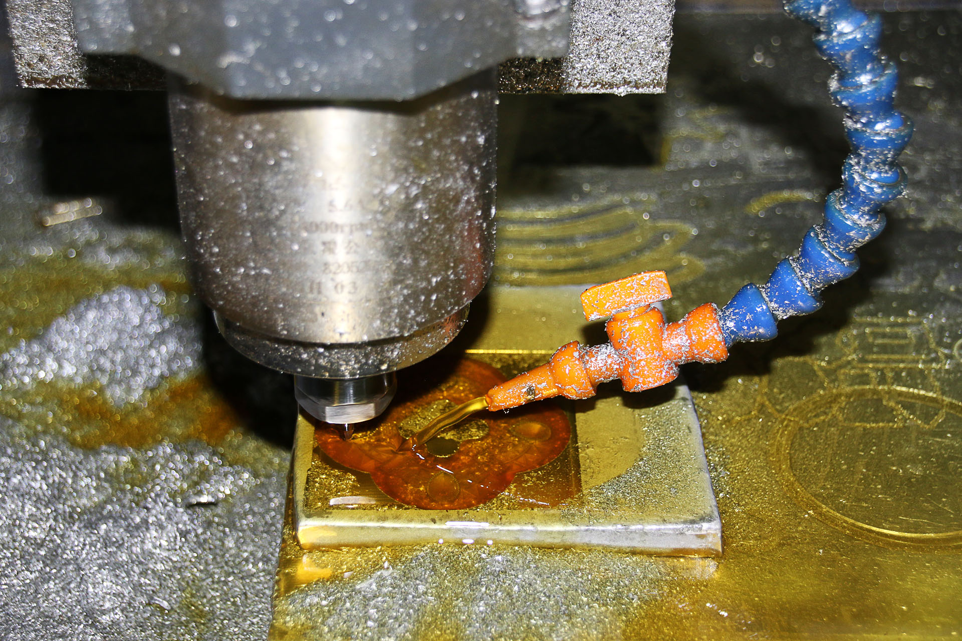
Features and Typical Components
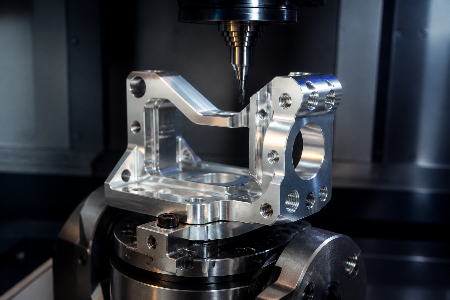
Important design attributes include the hole depth-to-diameter relationship, through or blind condition, intersecting passages, entrance geometry, exit breakthrough, internal finish, positional tolerance, and straightness requirement.
Typical components Typical examples include mold cooling passages, hydraulic components, actuator bodies, long fluid manifolds, aerospace structures, machine parts, heat-transfer blocks, and specialized fixtures.
Material Selection
Deep holes may be drilled in aluminum, carbon steel, alloy steel, stainless steel, tool steel, brass, copper alloys, titanium, and other materials, subject to tool and coolant strategy. Material hardness and chip form directly affect the process plan.
|
Material group |
What to consider |
Typical reason for selection |
|
Aluminum |
Machinability, thermal movement, cosmetic finish. |
Lightweight housings, brackets, fixtures, heat-management parts. |
|
Steel & stainless |
Strength, corrosion resistance, heat, chip control. |
Industrial, structural, fluid-system, precision mechanical parts. |
|
Brass, copper & titanium |
Conductivity, corrosion, strength-to-weight, cost. |
Fittings, electrical parts, high-performance or specialized components. |
|
Engineering plastics |
Stiffness, temperature, chemical environment, burr control. |
Insulating, lightweight, prototype, wear or fluid-contact parts. |
| MATERIAL NOTE The material must be selected against functional needs first. Machinability, heat, corrosion, weight, cost, and the desired surface treatment should then be reviewed together. |
Technical Planning and Quality
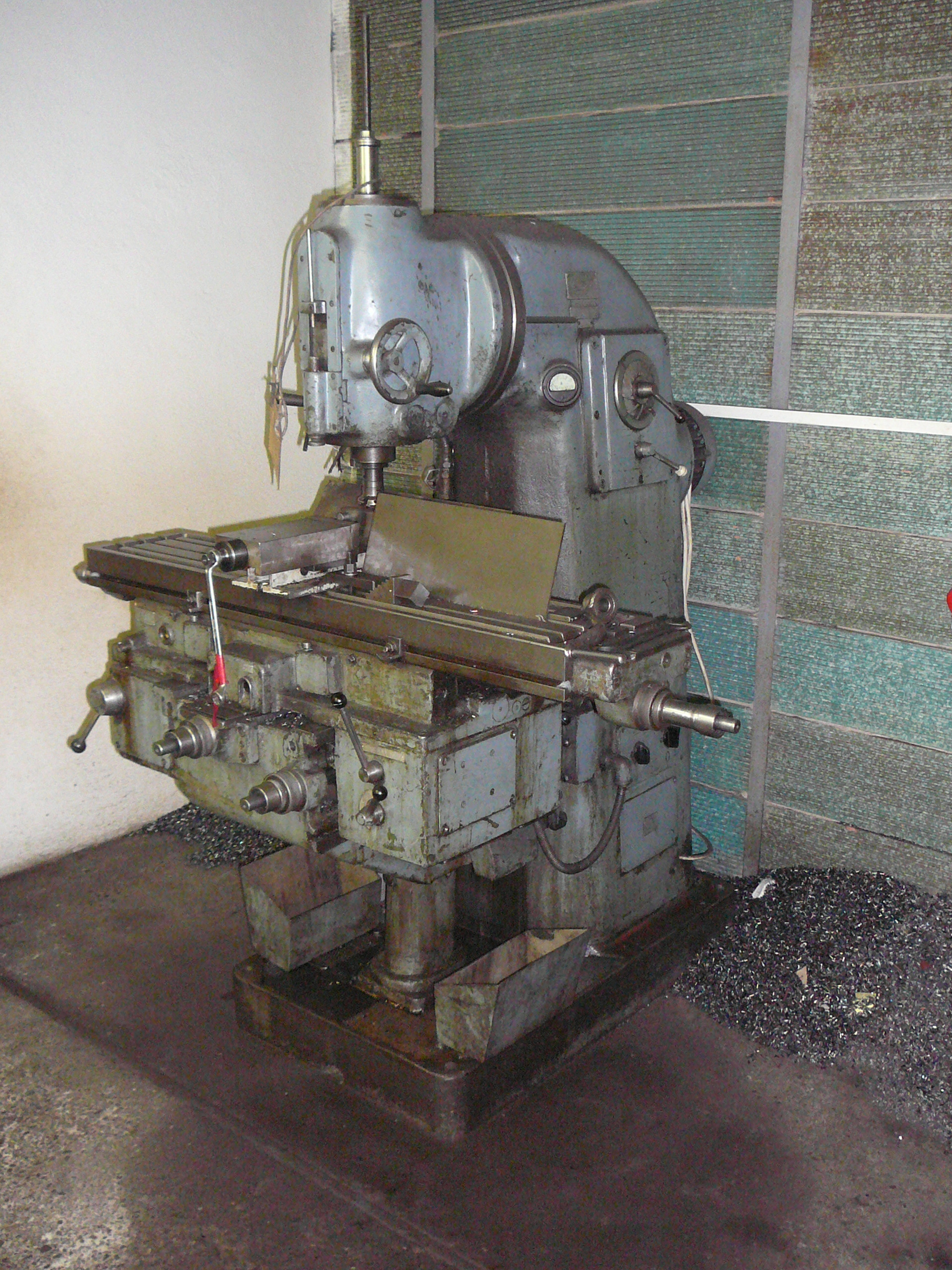
Manufacturing Considerations
Provide the exact hole depth, diameter, end condition, entry and exit surfaces, any cross holes, and the required relationship to external datums. If a tube or passage will carry fluid, specify cleanliness and deburring expectations for the internal intersections.
Quality and Inspection
Inspection can include depth, diameter, location, straightness, surface condition, bore cleanliness, and verification of intersecting-hole breakthrough. The measurement method should be chosen early for features that are inaccessible to standard gauges.
Surface Finish and Part Protection
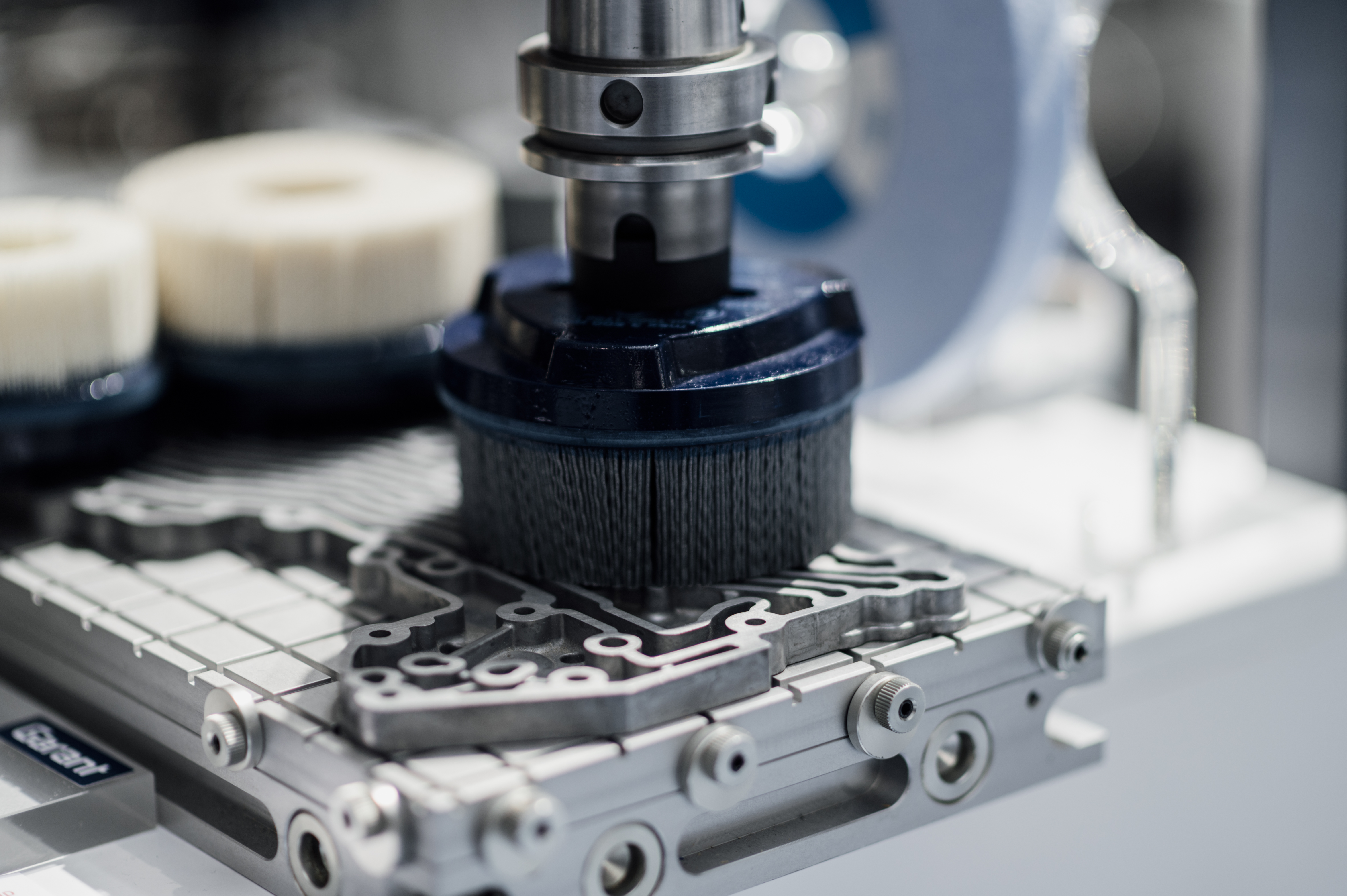
The primary concern is usually the condition of the hole itself, including burr removal at the entry, exit, and cross-hole intersections. External finishing may be applied after machining as long as critical passages are protected.
Before Production
A manufacturability review should confirm that the tolerance scheme is functional, the specified material is available, the workholding leaves access to critical faces, and the measurement plan can verify all requirements without ambiguity. Where an assembly interface is critical, provide the mating-part information or fit requirement.
|
DRAWING PRACTICE Call out the dimensions that matter to function. Avoid applying an unnecessarily tight general tolerance where only a limited number of features control the fit, motion, sealing, or alignment of the final assembly. |
Advantages and Applications
Why Select This Process
Deep-hole drilling provides a controlled approach to long internal passages that may be inefficient or unstable with general-purpose drilling alone. It supports designs that integrate cooling, flow, lubrication, or actuation into a compact component.
Application Context
Fluid power, molds and tooling, industrial machinery, energy systems, aerospace, medical equipment, thermal management, and custom automation are common application areas.
|
Application family |
Where the process adds value |
|
Prototype and product development |
Useful where a functional part, review sample, or process route must be validated before a larger production decision. |
|
Industrial and automation equipment |
Supports durable custom hardware, fixtures, housings, interfaces, shafts, passages, and assembly features. |
|
Precision and regulated equipment |
Supports geometry that must be documented through clear datums, material specifications, inspection requirements, and controlled finishing. |
When to Choose Another Process
Choose a deep-hole-specific strategy when the depth relative to diameter, straightness, chip evacuation, or internal cleanliness makes a standard drilling route unsuitable. A process review should confirm the feasible depth, tool type, and inspection plan.
|
QUOTE CHECKLIST Include model and drawing files, material grade, order quantity, material certification needs, finishing requirements, critical features, and target delivery date with the RFQ. |
Key Process Parameters
| Parameter | Typical Value |
|---|---|
| Diameter range | Ø1.5 mm to Ø50 mm standard; larger diameters quoted on application |
| Maximum depth-to-diameter ratio | Up to 100:1 with gun-drilling; 30:1–50:1 typical for BTA / ejector |
| Maximum hole depth | Up to 1,000 mm in a single pass; deeper holes reviewed per part |
| Diameter tolerance | ±0.025 mm standard; ±0.013 mm on request for precision bores |
| Surface finish | Ra 0.4–1.6 µm typical, depending on material, tool, and coolant |
| Straightness | 0.02–0.05 mm per 100 mm of depth; tighter alignment reviewed case by case |
| Entry surface | Pilot bore Ø0.5–2 mm or pre-drilled start; flat or contoured entry supported |
| Drilling methods | Gun-drilling, BTA, ejector, single-flute, and multi-flute deep-hole cycles |
| Coolant supply | High-pressure through-tool coolant, 70–150 bar for gun-drilling |
| Batch range | Single-piece prototypes through 5,000-piece production runs |
| Typical lead time | 7–15 working days for prototypes; 15–30 working days for production |
| Accepted CAD formats | STEP, IGES, X_T, Parasolid, native SolidWorks / CATIA / NX files |
Materials We Machine
- Carbon and alloy steels — 1018, 1045, 4140, 4340, EN24, EN26, P20, P20+Ni
- Stainless steels — 304 / 304L, 316 / 316L, 321, 347, 17-4PH, 15-5PH, 2205 duplex
- Tool and high-speed steels — A2, D2, H13, S7, M2, M42, T1
- Aluminum alloys — 6061-T6, 7075-T6, 2024-T3, 6082, 5052
- Titanium — Grade 2, Grade 5 (Ti-6Al-4V), Grade 9 (Ti-3Al-2.5V)
- Nickel-based alloys — Inconel 625, Inconel 718, Monel 400, Hastelloy C-276
- Copper and brass — C110 copper, C360 brass, C932 bearing bronze
- Cast irons and hardened alloys — gray iron GG25, ductile iron 60-40-18, ADI grades up to HRC 45
Standard Tolerances & Achievable Precision
Standard gun-drilling holds ±0.025 mm on diameter. Tight-tolerance work is achieved by selecting a more stable tool geometry, controlling coolant pressure, and verifying alignment of the part and spindle before the cut begins.
- Diameter: ±0.025 mm standard, ±0.013 mm on precision bores
- Depth: ±0.5 mm on holes up to 500 mm; ±1.0 mm above 500 mm
- Straightness: 0.02–0.05 mm per 100 mm, depending on material and depth
- Position: ±0.05 mm relative to the part datum, or as specified by GD&T
- Surface finish: Ra 0.4–1.6 µm as-drilled; finer finishes by reaming or honing
- Default tolerancing per ISO 2768-m where the drawing does not call out otherwise
Surface Finish Options
- As-drilled (gun / BTA) — typical Ra 0.4–1.6 µm internal wall
- Reaming or burnishing for closer tolerance and finer internal finish (Ra 0.2–0.8 µm)
- Honing for hydraulic or pneumatic bores requiring Ra below 0.4 µm and roundness under 5 µm
- Deburring and edge-breaking at entry and exit to control burrs on intersecting passages
- Bore cleaning and flushing to meet cleanliness specifications for fluid-power components
- External finishes: bead blast, anodize Type II / III, passivation, black oxide, powder coat, paint
- Electroplating options: zinc, zinc-nickel, nickel, chrome — applied after drilling where drawing requires
- Laser marking and engraving on external surfaces for part numbers and traceability
Quality Control & Inspection
Deep-hole features are inspected with methods chosen to match the part's tolerance and accessibility. For long or internal bores, special gauges and borescopes supplement standard hand tools.
- CMM measurement of external datums and entry / exit feature position
- Internal diameter gauges and air gauges for bore size and roundness
- Borescope visual inspection of internal wall condition, straightness indication, and intersections
- Surface roughness tester (profilometer) for internal wall finish where accessible
- Hardness tester for heat-treated or surface-hardened materials
- First-article inspection against the full drawing; in-process checks at drilling and finishing stages
- Final inspection report and material certification (EN 10204 3.1) on request
Design Considerations (DFM Tips)
- Define the depth-to-diameter ratio up front; ratios above 30:1 typically require gun-drilling or BTA and a guided start.
- Provide a flat, perpendicular entry surface — or specify a pre-drilled pilot — so the gun drill can start without wandering.
- For intersecting holes, indicate whether the secondary hole must be free of burrs and the tolerance on the intersection point.
- Avoid specifying the maximum possible depth in a single part if a stepped or cross-drilled alternative reduces risk and cost.
- Allow generous radii at the bottom of blind holes (≥ 0.5 × Ø) so the drill geometry can complete the cut cleanly.
- If the bore carries fluid, state cleanliness and surface-finish expectations — they drive the choice of drill, coolant, and any post-process.
- Hardened or difficult-to-machine alloys (Inconel, titanium, hardened tool steel) are best reviewed for feasibility before tooling is committed.
- Thin walls adjacent to a deep bore deflect during drilling; flag thin sections in the print so the process plan can support them.
- For very long holes, indicate the maximum acceptable entry / exit straightness deviation against the part datum.
Industries & Applications
- Aerospace — landing gear pins, hydraulic manifolds, actuator bodies, landing-gear trunnions
- Oil & gas — downhole tool barrels, drilling collars, valve bodies, flow-meter bodies
- Automotive and motorsport — crankshafts, drive shafts, gear blanks, injector bodies
- Hydraulics and pneumatics — hydraulic cylinder blocks, valve spools, pump housings
- Medical devices — surgical instrument shafts, bone-drill guides, cannulated instruments
- Energy — heat-exchanger tubesheets, nuclear component bodies, generator rotor cooling passages
- Mould and die — ejector pin holes, leader pin bores, cooling channels in die blocks
Frequently Asked Questions
What is the practical limit for hole depth?
Gun-drilling routinely reaches depth-to-diameter ratios of 100:1 in diameters below Ø20 mm. Beyond a metre, the part geometry, fixturing, and inspection method all start to dominate the process and the part is reviewed case by case.
How is straightness controlled on a long hole?
By setting a precise pilot, controlling coolant pressure, and matching the cutting parameters to the material. For critical bores we measure straightness with a bore gauge or a borescope and document the result against the part datum.
Can you deep-drill hardened parts?
Yes, up to about HRC 45–50 with the right tool geometry and coated drills. Above that, EDM or grinding of the bore is usually the cleaner route. Send the hardness specification with the drawing so we can recommend the right approach.
Do you handle intersecting and cross-drilled passages?
Yes. We plan tool entry / exit, chip evacuation, and any deburring or radius requirement at the intersection. If a fluid path is involved, cleanliness and deburr expectations are flagged at the quote stage.
What is the smallest diameter you can deep-drill?
Standard gun-drilling starts at Ø1.5 mm. Below that, EDM hole-popping or micro-machining is usually more reliable. We review the part and recommend the right method for the diameter, depth, and material.
What about cleanliness for hydraulic and fuel passages?
We finish with controlled flushing, ultrasonic cleaning where required, and borescope inspection. If a cleanliness spec (for example ISO 4406 or NAS 1638) applies, state it on the drawing so it is built into the inspection plan.
How to Get a Quote
Send the 3D model and 2D drawing with GD&T, the material grade and hardness condition, the order quantity, any required surface finish or cleanliness, and inspection requirements. For very deep holes, please flag intersecting features, fluid-path requirements, and entry / exit surface conditions up front.
You receive a written quote within one working day covering DFM feedback on hole geometry, the proposed drilling and inspection route, lead time, and unit price. Where there is a more cost-effective method — for example stepping a single very deep hole into two operations — it is called out before the quote is finalised.
Process Flow & Manufacturing Sequence
A deep-hole operation is planned around chip evacuation, coolant pressure, and tool guidance. The route below covers a typical gun-drilled or BTA-drilled hole from incoming stock to inspected bore. The actual sequence is tuned to the diameter, depth, and material.
- Stock and datum preparation — the blank is rough-machined, faced, and centred; any pre-existing datum face is verified square to the spindle axis so the drill enters on a controlled surface.
- Pilot bore (when required) — for very small diameters or hard entry surfaces, a short pilot hole is drilled to stabilise the gun drill and prevent wander at start.
- Workholding and alignment — the part is clamped in a V-block, steady-rest, or dedicated fixture; the spindle axis is aligned to the required entry position and the runout is recorded.
- Coolant system setup — high-pressure coolant is connected through the spindle or through the gun-drill body, the filter is checked, and pressure is set to the recommended range for the tool diameter.
- Pecking and feed strategy selection — the cycle is set to retract for chip break (gun drilling) or to feed continuously (BTA); spindle speed and feed are matched to the tool manufacturer data sheet.
- Pilot pass — a short, slow entry cut is made to seat the drill, confirm coolant flow, and check chip formation before the full-depth cycle starts.
- — Main drilling cycle — the gun drill or BTA head feeds to the target depth with controlled pecking for chip evacuation; coolant pressure and flow are monitored throughout the cycle.
- Exit and dwell — feed is reduced as the drill breaks through to control burr and exit straightness; the tool is retracted under coolant to clear chips from the bore.
- Secondary operations — reaming, honing, or burnishing is performed when the print calls for closer size, better roundness, or a finer internal finish.
- Cleaning and deburring — chips are flushed, the bore is blown out with clean coolant or air, and entry / exit edges are deburred to the print specification.
- Inspection and documentation — bore size, straightness, surface finish, and (if required) cleanliness are measured and recorded against the print and any customer spec.
Material Property Reference
| Material | Density (g/cm³) | Tensile Strength (MPa) | Yield Strength (MPa) | Hardness (HB) | Machinability (%) |
|---|---|---|---|---|---|
| Steel 1018 (cold-drawn) | 7.87 | 440 | 370 | 130 | 70 |
| Steel 4140 pre-hard (HRC 28–32) | 7.85 | 1,020 | 900 | 290 | 55 |
| Steel 4340 Q&T (HRC 28–34) | 7.85 | 1,100 | 1,000 | 320 | 50 |
| Stainless 304 / 304L | 8.00 | 580 | 290 | 170 | 45 |
| Stainless 316 / 316L | 8.00 | 580 | 290 | 170 | 40 |
| Stainless 17-4PH (H1150) | 7.78 | 1,070 | 1,000 | 330 | 38 |
| Tool steel D2 (annealed) | 7.70 | 760 | 450 | 220 | 30 |
| Tool steel H13 (annealed) | 7.80 | 760 | 470 | 230 | 35 |
| Aluminum 6061-T6 | 2.70 | 310 | 276 | 95 | 180 |
| Titanium Grade 5 (Ti-6Al-4V) | 4.43 | 950 | 880 | 330 | 30 |
| Inconel 718 (annealed) | 8.19 | 1,275 | 1,050 | 360 | 12 |
| Ductile iron 60-40-18 | 7.10 | 414 | 276 | 150 | 85 |
Cost Drivers & Lead Time Factors
Deep-hole cost and lead time are dominated by the depth-to-diameter ratio, the workpiece material and hardness, the straightness and finish requirements, and whether secondary finishing (reaming, honing) is part of the route. Tool life on gun drills and BTA heads is a key cycle-time driver; tight tolerance and tight straightness add setup, gauging, and trial-cut time.
| Scenario | Typical Lead Time | Primary Driver |
|---|---|---|
| Prototype, short D<30:1, common steel | 7–10 working days | Drill selection, setup, first-article bore inspection |
| Prototype, D > 50:1 or exotic alloy | 12–20 working days | Special gun drill, trial cuts, BTA head procurement |
| Production 50–500 pieces | 15–25 working days | Cycle time, drill life per piece, scheduled tool changes |
| Production 500–5,000 pieces | 20–35 working days | Multi-spindle scheduling, fixturing for batch loading, coolant management |
| Honed hydraulic bore (Ra < 0.4 µm) | +3–7 working days vs. baseline | Honing tool setup, abrasive selection, cleanliness verification |
| Hardened part, HRC 45–55 | +5–10 working days vs. baseline | CBN / coated tools, slower parameters, additional inspection |
| Intersecting / multi-passage bore | +3–8 working days vs. baseline | Sequence planning, intersection deburr, tool entry / exit strategy |
Common Defects & Prevention
| Defect | Cause | Prevention |
|---|---|---|
| Drill wander at entry | Irregular or angled entry surface, low pilot stiffness, or excessive initial feed | Machine a flat perpendicular starting face, drill a pilot, reduce entry feed, and check spindle runout |
| Chip evacuation failure | Insufficient coolant pressure, dull cutting edge, or excessive feed on long chips | Raise coolant pressure to spec, replace or redress the drill on schedule, and add peck cycles for long-chip materials |
| Hole taper | Drill wear, thermal growth, or deflection on slender workpieces | Replace the drill at rated life, use steady-rests, and check coolant temperature at the inlet and outlet |
| Bell-mouthing at exit | Drill exits into a soft or unsupported area, or breakthrough feed is too high | Support the part at the exit point, reduce feed in the final 1–2 mm of depth, and use a backing plate when possible |
| Poor straightness | Spindle-to-part alignment error, asymmetric cutting forces, or residual stress in the stock | Indicate the part in the fixture, run a pre-machining alignment cut, and stress-relieve stock where the print allows |
| Surface roughness / spiral marks | Vibration, built-up edge, or improper feed-to-speed ratio | Adjust cutting parameters to the tool maker's data sheet, switch to a coated tool, and verify coolant concentration |
| Drill breakage | Chip pack, sudden interruption of coolant flow, or excessive feed on a worn drill | Monitor coolant pressure interlock, replace drills at rated life, and use the manufacturer's recommended maximum feed |
| Coolant starvation in deep bore | Filter clog, line restriction, or inadequate pump capacity for the required flow | Service filters before each run, verify flow at the spindle, and use the tool maker's recommended coolant viscosity |
Comparison With Related Processes
| Aspect | Deep-Hole Drilling (this process) | Standard Twist Drilling | EDM Hole-Popping |
|---|---|---|---|
| Practical D/d ratio | Up to 100:1 (gun), 50:1 (BTA), deeper on review | ~10:1 without special technique | 100:1+ common; best for very small Ø |
| Surface finish | Ra 0.4–1.6 µm as-drilled; finer with honing | Ra 1.6–6.3 µm typical | Ra 0.4–1.6 µm recast layer; needs post-finish |
| Smallest diameter | ~Ø1.5 mm | ~Ø0.5 mm with micro drills | Down to Ø0.2 mm with starter hole |
| Best material fit | Steels, stainless, titanium, nickel alloys, aluminium | Steels, aluminium, cast iron; short holes | Any conductive material, including hardened |
| Cycle time impact | Cycle scales with depth and D; BTA faster on Ø20+ mm | Fast on shallow holes; slows dramatically with depth | Slow per part, but works where cutting cannot |
| When to choose | D/d above 10:1, deep fluid passages, precision bores in tough alloys | Shallow holes, prototyping, low-cost general use | Hardened or exotic alloys, micro-holes, non-conventional entry |
Industry Standards & Certifications
- ISO 9001:2015 — quality management system for all production work
- AS9100D — aerospace QMS for flight-critical bores in actuators, trunnions, and manifolds
- ISO 13485:2016 — medical device QMS for cannulated instruments and implant-related components
- IATF 16949 — automotive QMS for serial-production driveline and engine bores
- NADCAP AC7110/12 — special process accreditation for deep-hole drilling when required by aerospace primes
- ISO 4406 / NAS 1638 — fluid cleanliness codes for hydraulic and fuel-passage bores
- RoHS, REACH, and DFARS compliance on material sourcing
- ITAR registration for defence-related deep-hole work
- ASME Y14.5 and ISO 5459 for GD&T on bore position, straightness, and cylindricity
Packaging, Shipping & Documentation
Deep-hole parts are packed to protect bores from contamination, moisture, and impact. Bores are typically oiled or wrapped in VCI, then blocked or plugged if the print requires it. Long parts are supported along their length to prevent shipping distortion.
- Standard packaging — VCI paper or oil wrap on bores, foam end caps, individual wrapping, layer-pad cartons; long parts crated in V-block supports.
- Bore protection — plastic bore plugs, paper wraps, or taped caps on request to keep bores clean for hydraulic or pneumatic service.
- Shipping options — air freight, sea freight (FCL / LCL), road, and courier; EXW, FOB, CIF, and DAP incoterms supported.
- Standard documents — packing list, commercial invoice, certificate of conformance (C of C), material test certificate to EN 10204 3.1.
- Inspection documents — first-article report (AS9102 / PPAP), bore measurement report with diameter, straightness, and roundness data, surface-finish and cleanliness results, and borescope images when required.
- Traceability — lot and heat-number linkage from raw stock through drilling, heat-treat, finishing, and shipment; serialisation on request.
Related Capabilities & Cross-Services
Deep-hole work is normally part of a wider part process. The following capabilities are commonly combined with deep-hole drilling to deliver a finished, inspected component.
- Turning and CNC lathe work — pre-machining of the OD, flange, register, and seal faces before the deep bore is drilled.
- Milling (3-axis, 4-axis, 5-axis) — features on the part envelope that are not on the turning axis, and slots for fluid intersections.
- Boring and fine-boring — close-tolerance finishing of the bore after drilling for H-class fits and bearing seats.
- Reaming, honing, and burnishing — internal finishing to Ra below 0.4 µm, controlled roundness, and surface hardness.
- Thread milling and tapping — internal threads at the bore mouth, mounting threads, and cross-port threads.
- EDM (wire and sinker) — for very small holes, intersecting features in hardened material, and sharp internal corners.
- Heat treatment — through-hardening, case-hardening, induction hardening, and stress relief through approved partners.
- Surface finishing — passivation, nitriding, chrome plating, and internal coating for wear or corrosion resistance.
- Cleanliness verification — fluid flushing, ultrasonic cleaning, and lab cleanliness testing to ISO 4406 or NAS 1638.
- Assembly and pressure testing — sub-assembly of fittings, plugs, and ports, and hydrostatic / pneumatic pressure testing when the print requires it.

