
Engineering question
What must work when the part is real?
Tight Tolerance Parts
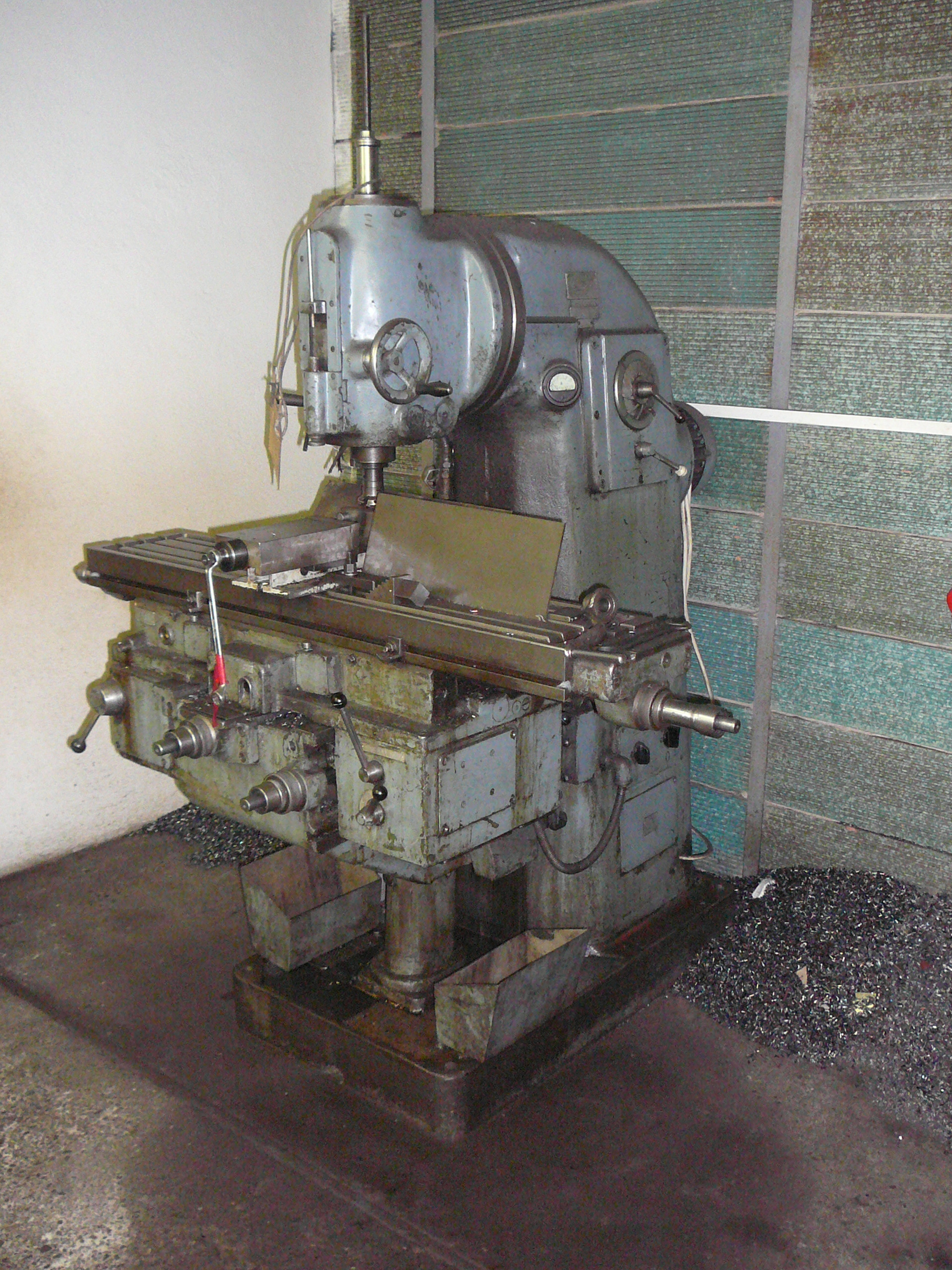
A source-aware reference guide to tolerance planning, datum schemes, inspection strategy, and the practical use of precision machining.
| Primary concern Use clear datums, dimension only the functional features tightly, specify geometric tolerances where relationship matters, and state the inspection method or report requirement for critical parts. Include mating part information whenever possible. | Validation lens Inspection may use calibrated gauges, CMM measurement, bore gauges, micrometers, optical measurement, surface comparison, or functional gauges depending on the feature. The plan must be proportionate to the tolerance and quantity. |
This page uses a design-review opening so the service reads like an engineering brief rather than a repeated product brochure.
Functional Tolerances, Not Blanket Tolerances
Tight-tolerance parts are components with specific dimensions or geometric relationships that must remain close to the intended design for the assembly to function. The correct approach is not to tighten every dimension; it is to identify the features that control fit, motion, sealing, alignment, or interchangeability and then choose a process and inspection plan that can verify them.
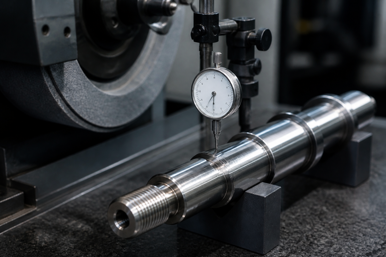
What is the part proving?
A focused tolerance plan reduces unnecessary cost while preserving the dimensions that determine whether the assembly works. It also creates a clearer basis for manufacturing and acceptance.
| Design question | Review before machining |
|---|---|
| Which feature controls function? | Use clear datums, dimension only the functional features tightly, specify geometric tolerances where relationship matters, and state the inspection method or report requirement for critical parts. Include mating part information whenever possible. |
| What is a successful output? | Inspection may use calibrated gauges, CMM measurement, bore gauges, micrometers, optical measurement, surface comparison, or functional gauges depending on the feature. The plan must be proportionate to the tolerance and quantity. |
Datum Strategy and Feature Hierarchy
Critical requirements can include close diameters, precision bores, flatness, parallelism, position, profile, runout, mating interfaces, wall thickness, and controlled surface condition.
Typical part context
Typical parts include bearing housings, sealing interfaces, locating fixtures, optical or sensor mounts, medical components, precision shafts, valve parts, and calibration or measurement hardware.
Material decision
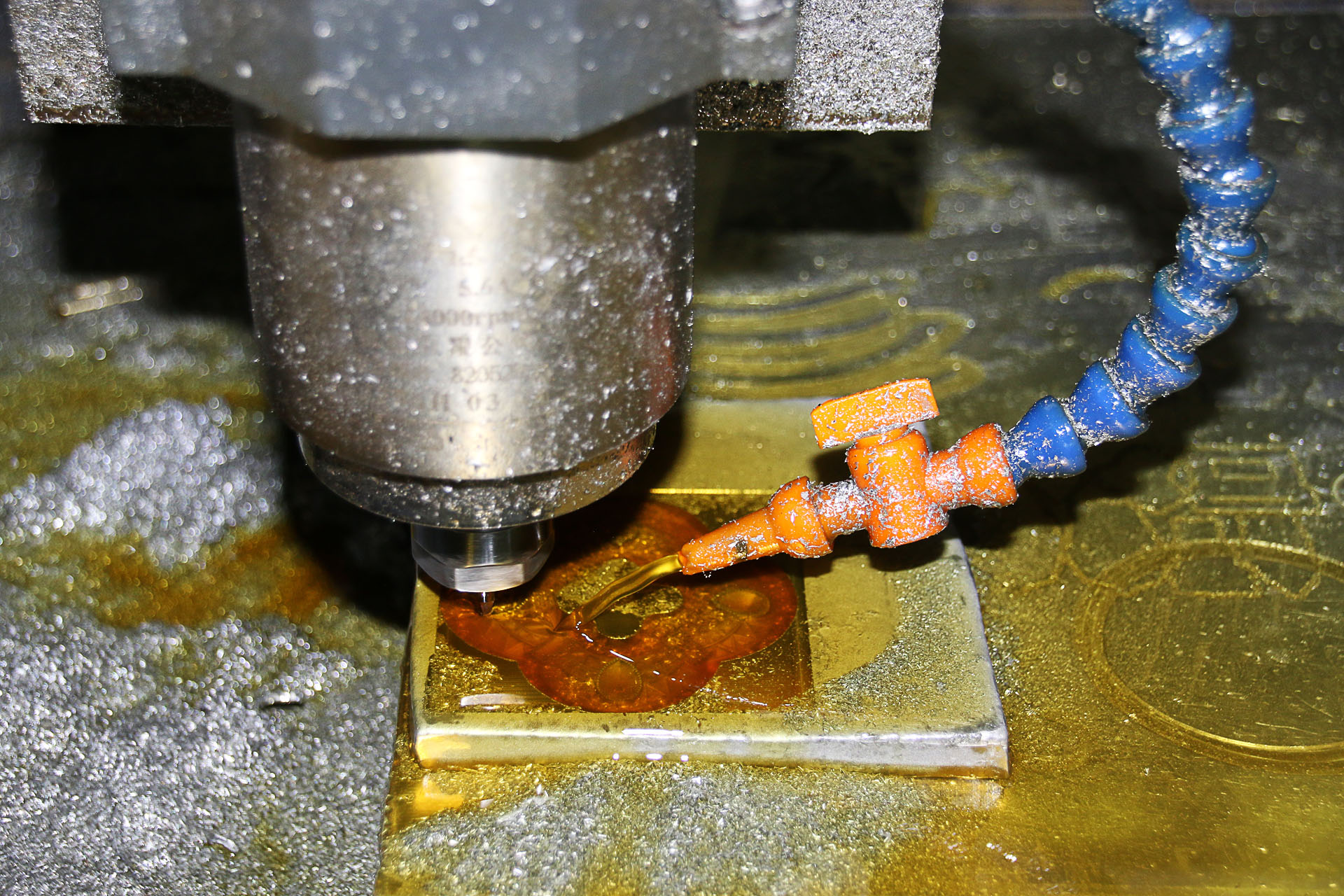
Material selection must include stability as well as strength or corrosion resistance. Heat treatment, residual stress, plating, anodizing, and temperature-sensitive materials should be considered in the tolerance stack-up.
Design signal: Make critical datums, small or delicate features, and finish-sensitive areas explicit. They should drive the process, not appear as a late exception.
Inspection Evidence and Revision Control
The route begins with drawing review and a datum hierarchy. Workholding and machining sequence are selected to protect the controlling relationships, followed by in-process checks and final inspection of the features that carry the functional tolerance.
Quality plan
Inspection may use calibrated gauges, CMM measurement, bore gauges, micrometers, optical measurement, surface comparison, or functional gauges depending on the feature. The plan must be proportionate to the tolerance and quantity.
After the machining operation
Finishing can change size, texture, or corrosion resistance. Define which surfaces are cosmetic and which must be masked, post-processed, or verified after finishing.
| Release item | Purpose |
|---|---|
| Controlled model and drawing | Makes the test or production intent traceable. |
| Acceptance method | Confirms that a critical feature can be measured in the way the design expects. |
| Learning loop | Captures changes needed before the next prototype, build, or released run. |
Choosing the Right Precision Route
Common contexts include aerospace, robotics, medical equipment, precision automation, energy systems, measurement devices, and custom industrial hardware.
When another route may be better
Use a tight-tolerance route when function demands it and the measurement plan is defined. General machining tolerances are normally more economical for noncritical dimensions.
RFQ check: Include the job's true objective: fit check, material test, production release, pilot quantity, inspection record, or a combination of these.
Key Process Parameters
| Parameter | Typical Value |
|---|---|
| Dimensional tolerance | ±0.0125 mm standard, ±0.005 mm precision, ±0.0025 mm ultra-precision |
| GD&T capability | True position, concentricity, perpendicularity, parallelism, profile, runout all to sub-0.01 mm |
| Surface finish Ra | 0.4 μm to 1.6 μm as-machined; 0.05 μm to 0.2 μm after grinding or lapping |
| Min feature size | 0.5 mm wall / 0.3 mm slot typical, 0.1 mm with micro tooling |
| Max part envelope | Up to 800 mm × 500 mm × 400 mm (3-axis); larger on 5-axis and large-format machines |
| Min hole diameter | 0.3 mm with micro drills / EDM |
| Positional accuracy | ±0.005 mm true position on critical features |
| Batch range | 1 prototype piece to 5,000+ production parts |
| Standard lead time | 5–10 days for prototype, 2–4 weeks for production orders |
| Accepted file formats | STEP, IGES, X_T, CATIA, SolidWorks native, DWG/DXF, PDF drawing |
| Typical machines | DMG MORI DMU 50 / DMU 65, Mazak Integrex, Hermle C250/C400, Makino PS65, OKK VP-400, with thermal-stable environments and optional 5-axis trunnion tables |
Materials We Machine
- Aluminum alloys – 6061-T6, 7075-T6, 2024-T3, MIC6, 5052, 6082 for lightweight, dimensionally stable parts.
- Hardened tool and die steels – D2, A2, S7, H13, P20, SKD11, SKD61 (up to 62 HRC).
- Stainless steels – 303, 304, 316/316L, 410, 416, 420, 17-4 PH (H900–H1150), 15-5 PH.
- Carbon and alloy steels – 1018, 1045, 4140, 4340, 8620 (annealed or pre-hardened).
- Bearing and spring steels – 52100, 1095, 1074, 301, 302, 17-7 PH.
- Titanium – Grade 2, Grade 5 (Ti-6Al-4V), Grade 5 ELI for medical and aerospace.
- Engineering plastics – PEEK, Torlon, Delrin (POM-C / POM-H), UHMW-PE, PVC, acrylic.
- Magnesium and copper alloys – AZ31, C110, C360 brass for selected applications.
- Inconel and other super alloys – 625, 718, 825, Waspaloy, MP35N.
Standard Tolerances & Achievable Precision
Tight-tolerance machining combines stable tooling, controlled environments, and grinding or lapping when needed. Achievable tolerances depend on the geometry, material, and chosen process sequence.
- ±0.05 mm standard CNC milling/turning tolerance (ISO 2768-m default).
- ±0.025 mm precision tolerance on most features without secondary finishing.
- ±0.0125 mm tight tolerance on controlled features with CMM-verified process.
- ±0.005 mm ultra-precision on datums, bearing seats, and reference surfaces.
- ±0.0025 mm to ±0.001 mm achievable with grinding, lapping, or honing as a final step.
- ISO 2768-f on critical callouts; full GD&T (ASME Y14.5) including true position, profile, runout, and concentricity available.
- Part-to-part repeatability ±0.005 mm typical on 3-axis and 5-axis production runs.
Surface Finish Options
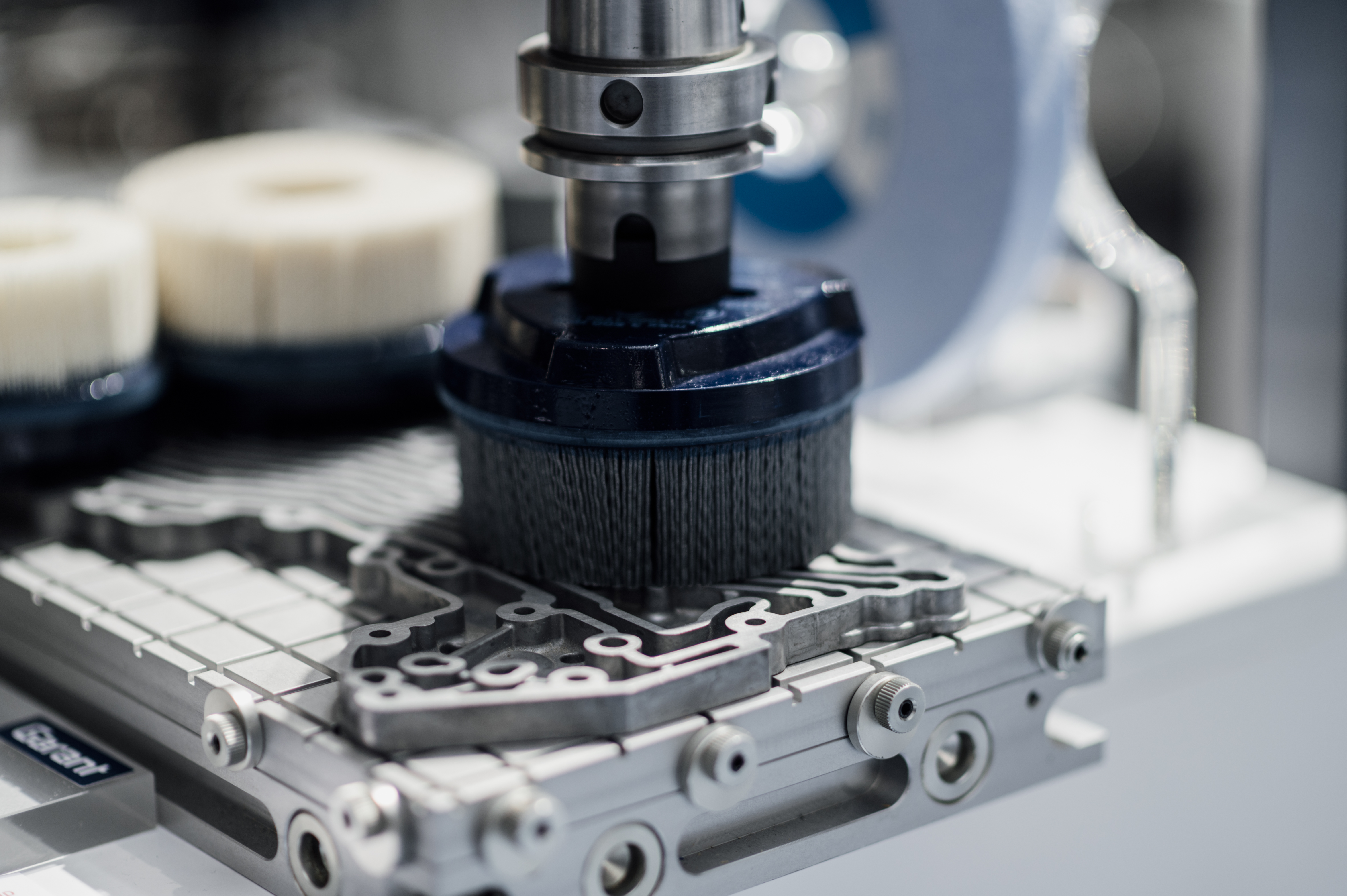
- As-machined – 0.8 μm to 1.6 μm Ra on aluminum, 0.4 μm to 0.8 μm Ra on steel.
- Fine machining – controlled step-down and finish pass for 0.2 μm to 0.4 μm Ra.
- Surface grinding – 0.2 μm to 0.4 μm Ra for flat references and datums.
- Cylindrical / centerless grinding – 0.1 μm to 0.4 μm Ra on round features.
- Lapping and honing – 0.02 μm to 0.1 μm Ra for sealing and bearing surfaces.
- Bead blast (glass bead / aluminum oxide) – uniform matte finish, no dimensional change.
- Anodize (Type II / Type III hard anodize) – on aluminum alloys with masking of critical features.
- Electroless nickel – uniform thickness on complex geometries, with post-grinding if needed.
- Hard chrome plating – on pre-machined steel with final grind to size.
- Passivation – ASTM A967 / A380 on stainless steel.
- Black oxide / manganese phosphate – MIL-DTL-13924D or equivalent.
- Powder coat and wet paint – with plug masking of precision features.
- Polishing and mirror finishing – on stainless or aluminum decorative parts.
- Laser engraving and laser marking – part numbers, scale marks, and traceability on shoulders or flat faces.
Quality Control & Inspection
Tight-tolerance work requires closed-loop inspection. The following equipment and processes are part of our standard QA scope:
- CMM (Zeiss Contura, Hexagon, Mitutoyo) – full GD&T verification, datum alignment, and 3D feature measurement.
- Surface roughness tester – Mitutoyo SJ-411, Mahr Pocket Surf for Ra, Rz, and profile traces.
- Hardness tester – Rockwell, Vickers, and Brinell for incoming and post-machining verification.
- Calipers and micrometers – 0.001 mm resolution for in-process checks.
- Bore gauges and pin gauges – for hole size and location verification.
- Optical comparator and vision systems – for profile, edge break, and chamfer inspection.
- First-article inspection (FAIR / AS9102, PPAP) – full dimensional report before production run.
- In-process checks – defined measurement points during the run to detect drift.
- Final inspection report – digital report with measured values, CMM PDF, photographs, and material / heat-treat certificates.
Design Considerations (DFM Tips)
- Identify the critical features clearly on the drawing – call out which features drive the tolerance budget (e.g. bearing seat, sealing face, datum).
- Establish a primary and secondary datum system – tie GD&T to functional references, not arbitrary stock surfaces.
- Allow uniform wall thickness where possible – reduces distortion during heat treat and minimizes deflection in machining.
- Specify tight tolerances only where required – over-tolerance increases cost, lead time, and risk of rejection.
- Use standard tooling sizes where possible – metric or imperial standard drills, taps, and reamers reduce NRE and improve tolerance.
- Avoid deep narrow cavities – 3× diameter or shallower is a safe rule for milling; deeper cavities may need EDM.
- Add fillets at internal corners – a 0.5 mm minimum radius reduces stress concentration and allows cutter access.
- Plan heat treat before final machining – machine near-net, heat treat, then finish grind or lap critical features.
- Use datums that survive finishing – precision reference surfaces must remain accessible after coating, plating, or polishing.
- Mark inspection features on the drawing – identify how each critical dimension will be measured to avoid ambiguity.
Industries & Applications
- Aerospace – actuator housings, hydraulic manifolds, sensor brackets, structural fittings.
- Medical and life sciences – instrument housings, surgical hand-pieces, implant trial hardware, diagnostic equipment components.
- Semiconductor – chamber fittings, gas-line components, wafer-handling fixtures, electrostatic chuck bodies.
- Optical and photonics – lens mounts, mirror holders, kinematic bases, optical benches.
- Automotive – sensor housings, gearbox components, EV battery and motor components, prototype racing parts.
- Robotics and automation – precision gear-housing components, end-effector plates, locating blocks.
- Energy – downhole tool components, turbine hardware, fuel-cell plates, instrumentation bodies.
- Metrology and inspection – gauge blocks, calibration fixtures, datum plates, CMM fixtures.
Frequently Asked Questions
What tolerance can you hold without secondary grinding?
±0.0125 mm is a realistic precision tolerance on most CNC-machined features in aluminum, steel, and stainless. Tighter tolerances on critical features are typically achieved with a finish-grind or lap operation.
Do you work to GD&T on the drawing?
Yes. We follow ASME Y14.5 GD&T callouts including true position, profile, runout, perpendicularity, and datum reference frames. First-article inspection reports document each feature against its GD&T callout.
How do you control dimensional stability?
We use thermal-stable machine tools, calibrated tools, controlled fixturing, low-stress tool paths, and material-specific cutting parameters. For critical features we add CMM verification and, when needed, a stress-relief or stabilization step before final machining.
Can you produce a single prototype to tight tolerances?
Yes. We routinely machine one-off prototypes at ±0.0125 mm or tighter, with a full CMM inspection report. Lead time is typically 5–10 working days depending on material availability and complexity.
What inspection documentation do you provide?
Standard inspection report with measured values, surface finish, and material certs. Optional: full AS9102 / PPAP first-article inspection, CMM PDF, photographs, and traceability to raw material heat / batch numbers.
Which materials are most difficult to hold tight tolerances on?
Titanium and Inconel are the most challenging because of spring-back, work-hardening, and heat generation. Distortion-prone materials like 17-4 PH also need stress relief before finish machining. We adjust the process plan to compensate.
How to Get a Quote
Send your 3D CAD file (STEP, IGES, X_T, or native), 2D drawing with GD&T, material grade and condition, lot size, target tolerances, surface finish, and any heat treat or coating requirements. We return a DFM review focused on tolerances, datums, and feature manufacturability, a realistic lead time, and a unit price broken down by raw material, machining, inspection, finishing, and documentation.
Process Flow & Manufacturing Sequence
Tight-tolerance machining is a coordinated process chain that begins with a clear functional understanding of the part and ends with metrology-verified features. The exact operations depend on whether the part is turned, milled, or a combination, but the sequence below covers the standard route for a 3-axis / 5-axis milled or turned feature with selected critical tolerances.
- RFQ review and tolerance plan – Drawing is reviewed against the mating part and assembly. Critical, functional, and reference features are flagged, and the inspection method for each is agreed up-front.
- Material selection and stock verification – Bar, billet, or plate is sourced with MTC. For stress-relieved or pre-hardened stock, a stress-relief certification is captured.
- Programming and CAM simulation – Tool paths are written with stock-aware roughing, rest-material machining, and finish strategies that match the GD&T (e.g. trochoidal milling for hard pockets, parallel finishing for flatness).
- Workholding and fixture design – Soft jaws, vacuum chucks, fixture plates, or 4th-axis trunnions are designed to expose all critical features with a single setup or a controlled secondary setup that preserves the datum chain.
- Thermal stabilization – Stock is brought to shop temperature 24 hours before cutting; the machine is warmed up on a program that replicates the part envelope.
- Rough machining – Aggressive MRR with indexable or solid-carbide tools leaves a uniform 0.2–0.5 mm stock for finish features and 0.05–0.2 mm for finishing on hard materials.
- Stress relief (inter-stage) – For parts where material removal is large, an inter-stage stress relief at 580–620 °C stabilizes the geometry before finish cutting.
- Semi-finish machining – Tool paths approach final geometry to within 0.05–0.1 mm, leaving a controlled, uniform stock for finishing.
- Finishing – Light depth of cut, low feed, sharp tools, and where required, trochoidal or peel strategies hold the part within tolerance on a single setup.
- Secondary finishing – Grinding, honing, lapping, EDM, or micro-machining steps are applied to features that exceed turning or milling capability (e.g. sub-5 μm flatness, sub-0.005 mm cylindricity).
- Datum preservation – All critical features are referenced to a single primary datum (or a defined datum chain) so that inspection matches the assembly reference.
- Pre-inspection cleaning – Aqueous wash and dry, plus deburr by hand or controlled tumble, to remove any chip or oil that would distort measurement.
- In-process inspection – Datums, bore diameters, and critical distances are checked at defined intervals; SPC data captured for production lots.
- Final inspection – CMM, profile projector, optical comparator, or calibrated gauges against the print. Full AS9102 first-article on the first part of a lot.
- Marking, packaging, and release – Laser marking on a designated feature; clean packaging; C of C and supporting reports issued.
Material Property Reference
Reference property values for materials commonly run as tight-tolerance machined parts. Machinability rating is referenced to AISI 1212 at 100%; lower values mean more rigid setups, slower cutting, and higher tool wear.
| Material | Density (g/cm³) | Tensile Strength (MPa) | Yield Strength (MPa) | Hardness (HB) | Machinability Rating (%) |
|---|---|---|---|---|---|
| Aluminum 6061-T6 | 2.70 | 310 | 276 | 95 | 180 |
| Aluminum 7075-T6 | 2.81 | 572 | 503 | 150 | 170 |
| Aluminum MIC6 (cast tool & jig plate) | 2.70 | 240 | 170 | 75 | 200 |
| Brass C360 (free-machining) | 8.50 | 510 | 380 | 130 | 100 |
| Copper C110 (ETP) | 8.94 | 220 | 70 | 50 | 20 |
| Carbon steel 1018 (cold drawn) | 7.87 | 470 | 400 | 140 | 78 |
| Alloy steel 4140 (annealed) | 7.85 | 655 | 415 | 200 | 60 |
| Alloy steel 4140 (Q&T 28–32 HRC) | 7.85 | 1020 | 900 | 290 | 50 |
| Tool steel D2 (Q&T 60 HRC) | 7.70 | 1860 | 1650 | 620 (HV) | 25 (grinding/EDM) |
| Stainless 304 (annealed) | 8.00 | 620 | 290 | 180 | 45 |
| Stainless 17-4 PH (H900) | 7.78 | 1380 | 1280 | 420 | 40 |
| Titanium Grade 5 (Ti-6Al-4V) | 4.43 | 950 | 880 | 335 | 22 |
| Inconel 718 (aged) | 8.19 | 1430 | 1180 | 460 | 12 |
| PEEK (unfilled) | 1.30 | 100 | — | M99 (Rockwell) | — (special tooling) |
Cost Drivers & Lead Time Factors
Tight-tolerance work is sensitive to setup, fixturing, and inspection. The same nominal part can be 2–5× more expensive when one feature is held to ±0.005 mm versus ±0.05 mm. The numbers below are typical for a job-shop environment with CMM verification.
| Scenario | Quantity | Typical Lead Time | Primary Cost Drivers |
|---|---|---|---|
| Aluminum prototype, ±0.05 mm, no GD&T | 1–5 off | 3–5 working days | Programming, soft jaws, single-setup cutting |
| Stainless part, ±0.025 mm, GD&T | 1–10 off | 5–10 working days | CMM time, multiple datums, slower cutting |
| Hardened steel, ±0.005 mm, AS9100 | 5–20 off | 2–3 weeks | Heat-treat, grinding, FAIR, full certs |
| 5-axis medical part, ISO 13485 | 10–50 off | 2–4 weeks | 5-axis sim, validated process, FDA-traceable material |
| Titanium aerospace bracket, ±0.0125 mm | 20–100 off | 3–4 weeks | Material cost, tool wear, special fixturing |
| Inconel valve body, ±0.025 mm, AS9100 | 5–25 off | 3–5 weeks | Low MRR, ceramic insert cost, swarf control |
| Production lot, ±0.0125 mm, PPAP | 500–5,000 off | 4–6 weeks | Tool life, gauge calibration, control plan |
| Sub-micron reference (lapping, μ-EDM) | any | +1–2 weeks vs standard | Special process, environmental control, traceability |
Common Defects & Prevention
| Defect | Cause | Prevention |
|---|---|---|
| Out-of-tolerance dimension | Tool wear, machine thermal drift, fixturing deflection, programming error, wrong stock allowance | Use tool-length compensation with probes, run warm-up programs, verify fixturing rigidity, use rest-material-aware CAM |
| Geometric tolerance (flatness, parallelism, perpendicularity) out of spec | Clamping distortion, part fixturing on un-machined reference, machine axes out of alignment, fixturing stack-up error | Define functional datums, machine a true reference first, square the vise or fixture to a calibrated test bar, use a single-setup strategy |
| Chatter / poor surface finish | Excessive tool overhang, low rigidity, aggressive parameters, worn spindle bearings | Shorten tool overhang, switch to a more rigid tool, reduce radial engagement, use a long-reach toolholder, check spindle |
| Burr at edges and intersections | Tool exit condition, dull tools, sharp inside corners on the print, no chamfer callout | Use chamfer mills, add a deburr cycle, request chamfers on the print, replace tools at planned intervals |
| Workpiece distortion after machining | Residual stress from prior rolling/forging, heavy material removal, aggressive heat input | Stress-relieve before finish, use balanced roughing strategies, machine symmetric features in balanced passes |
| Inconsistent feature size lot-to-lot | Tool wear, coolant temperature variation, incoming stock hardness variation, lack of in-process gauging | Plan tool changes, stabilize coolant, in-process gauge feedback with offset compensation, SPC on critical features |
| Hole or slot true position out of spec | Loose tool in holder, fixture repeatability, machine positioning error, stacked tolerances | Run ballbar / laser calibration, use shrink-fit or hydraulic holders, fixture repeatability check, calculate datum-shift error |
| Surface integrity / metallurgical damage | Excessive heat input, no coolant, dull tools, wrong geometry on the cutting tool | Use sharp tools with proper rake, high-pressure coolant, trochoidal strategies on hard material, consider grinding for sub-finish on critical features |
Comparison With Related Processes
| Aspect | Tight-Tolerance Machining | Alternative | When to Choose |
|---|---|---|---|
| Geometry complexity | 3-axis to 5-axis prismatic parts, pockets, slots, holes, bores, complex turned features | EDM: any conductive material, sharp internal corners, very deep features | Choose machining for general geometry and higher throughput; EDM for sharp inside corners or features unreachable by tools |
| Sub-5 μm flatness / parallelism | Achievable on hard material with light finish passes; grinding for the last 5–10 μm | Surface grinding / blanchard grinding: sub-2 μm flatness on hard materials | Choose grinding as a final step for tight flatness on hard materials; machining is enough for soft-material references |
| Hard material capacity | Up to ~62 HRC with coated carbide, slow MRR | Wire / Sinker EDM: any hardness, no cutting force | Choose EDM for high-hardness features with sharp inside corners; machining when geometry and throughput allow |
| Lead time for prototypes | 3–10 days for typical parts | Additive manufacturing: 1–3 days for simple parts | Choose additive for geometry-driven prototypes or for plastics; machining for functional metal prototypes |
| Documentation rigor | AS9102 / PPAP / ISIR, full traceability | Standard C of C only for prototype / casting / molding | Choose tight-tolerance machining when the customer requires a documented, inspected, repeatable process |
Industry Standards & Certifications
- ISO 9001:2015 – QMS baseline across all industries.
- AS9100D – Required for aerospace structural, hydraulic, and engine parts.
- ISO 13485:2016 – Required for medical devices, surgical instruments, and implant-related components.
- IATF 16949 – Automotive QMS for safety-critical driveline and chassis parts.
- NADCAP – Special-process accreditation for any heat treat, plating, or non-destructive testing used in the route.
- RoHS & REACH – Required for European markets; restricts substances in any coating or finishing applied to the part.
- ITAR – Required for defense articles and controlled parts.
- ISO 2768-1 / ISO 2768-2 – General tolerance (medium / fine) for un-toleranced dimensions.
- ASME Y14.5-2018 – GD&T symbol and rule set for datums, runout, profile, and position.
- ISO 5459 – Datum reference convention for inspection and tooling.
- SAE AS9102 – First-article inspection report for aerospace.
- AIAG PPAP / APQP – Production part approval process for automotive.
- ISO 10360 – CMM acceptance test applied to inspection equipment used for the part.
Packaging, Shipping & Documentation
Tight-tolerance parts are usually expensive and small-batch, so packaging is sized to protect functional features from contact and corrosion. Documentation is comprehensive because the parts are typically qualified through a controlled gate.
- Individual wrapping – Each part wrapped in VCI paper or anti-static foam for sensitive electronic or surface-critical parts.
- Custom foam cavity – CNC-machined foam insert holds the part in a defined orientation; used for medical and aerospace parts.
- Clean-room bagging – ISO 7 / ISO 8 clean-room packaging for medical implants and semiconductor parts.
- Outer carton – Double-wall corrugated, edge protectors, foam-in-place for delicate assemblies.
- Shock & tilt indicators – Required for high-value parts, defense articles, and medical deliveries.
- Labeling – Per-piece label with part number, lot, and serial (when serialized); outer carton labeled with revision, weight, dimensions, and HS code.
- Shipping options – Hand-carry for critical spares, expedited air for short lead times, standard freight for production lots.
- Standard documents – Certificate of Conformance (C of C) with drawing and revision reference.
- Material certificate – Mill Test Certificate (MTC) or 3.1 / 3.2 inspection certificate per EN 10204.
- Heat-treat / surface certificate – When heat treat, plating, or coating is in scope.
- First-article report – AS9102 FAIR or equivalent CMM / ISIR report on the first part.
- CMM / inspection report – Full PDF with measured values, GD&T feature callouts, and probe / calibration data.
- Traceability – Heat number, lot, operator, and machine logs retained in the digital traveler for the contracted retention period.
Related Capabilities & Cross-Services
Tight-tolerance work is rarely a single process. The capabilities below are commonly combined on a single part to hit functional and geometric requirements efficiently.
- 3-, 4-, and 5-axis CNC milling – Prismatic features, complex contours, multi-face parts.
- CNC turning and mill-turn – Turned features in the same setup as milled features.
- Swiss-type turning – Small-diameter, long-aspect-ratio features for medical and electronics parts.
- Surface and cylindrical grinding – Final finish on hard materials and tight flatness / cylindricity.
- Wire EDM and Sinker EDM – Sharp internal corners, deep cavities, and hardened features.
- Honing – Cylindrical bore refinement for hydraulic and pneumatic components.
- Lapping – Sub-micron flatness and surface finish on gauges and reference hardware.
- Heat treatment – Through-hardening, case-hardening, nitriding, and aging coordinated with the machining sequence.
- Passivation, electropolish, and anodizing – Surface conversion on stainless, aluminum, and titanium.
- Plating (chrome, electroless nickel, gold, silver) – Functional and decorative coatings applied before or after final machining.
- CMM and optical metrology – Calibrated equipment with full PDF reports and digital archive.
- PPAP / APQP and FAI support – Production part approval and first-article inspection documentation.
- DFM review and tolerance stack-up analysis – Engineering feedback before the print is released for production.

