
Part Suitability for Centerless Support
Centerless grinding is a method for finishing external cylindrical surfaces without holding the part between centers. The workpiece is supported on a work-rest blade and controlled between a grinding wheel and regulating wheel. It is often considered for repeat quantities of straight, slender, or small-diameter round parts.
Feature families
Common feature families include straight outside diameters, stepped pins, dowel-like forms, shafts, rods, rollers, sleeves, and small cylindrical components requiring repeatable size.
| Functional outcome | What the drawing should identify |
|---|---|
| Fit / movement / sealing | Review length-to-diameter ratio, shoulders, interruptions, grooves, chamfers, allowable stock, and where the part can contact the work-rest blade. Design details that prevent stable support must be resolved before production. |
| Part context | Representative parts include pins, shafts, valve elements, motor components, sleeves, guide rods, fastener-like hardware, medical or instrumentation components, and production precision blanks. |
Through-Feed and In-Feed Planning
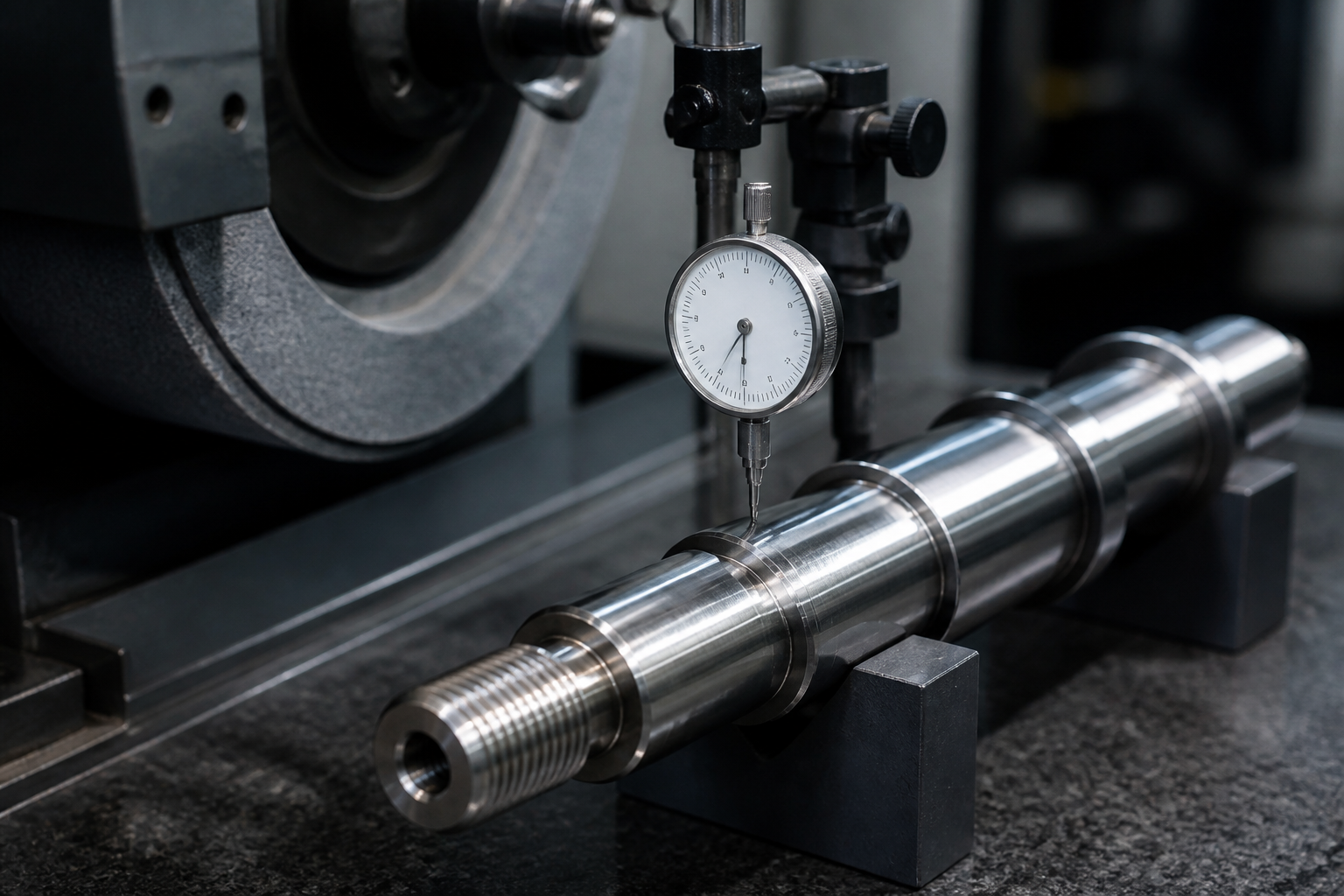
A process review selects the wheel, regulating-wheel condition, work-rest geometry, infeed or through-feed method, and stock allowance. The part is guided through or fed into the grinding zone so the target diameter, straightness, finish, and consistent material removal can be controlled.
| Before grinding | During grinding | After grinding |
|---|---|---|
| Stock allowance, datums, stable support | Wheel condition, heat, passes, coolant, geometry checks | Deburr, protect, inspect, package |
PROCESS RISK: Heat, thin sections, interrupted surfaces, and unstable support can matter as much as nominal dimension.
Diameter Stability and Edge Detail
Steels, stainless steels, tool steels, alloys, and certain nonferrous materials may be suitable. Geometry, material condition, hardness, and the desired surface condition determine whether a centerless route is practical.
Finish and protection
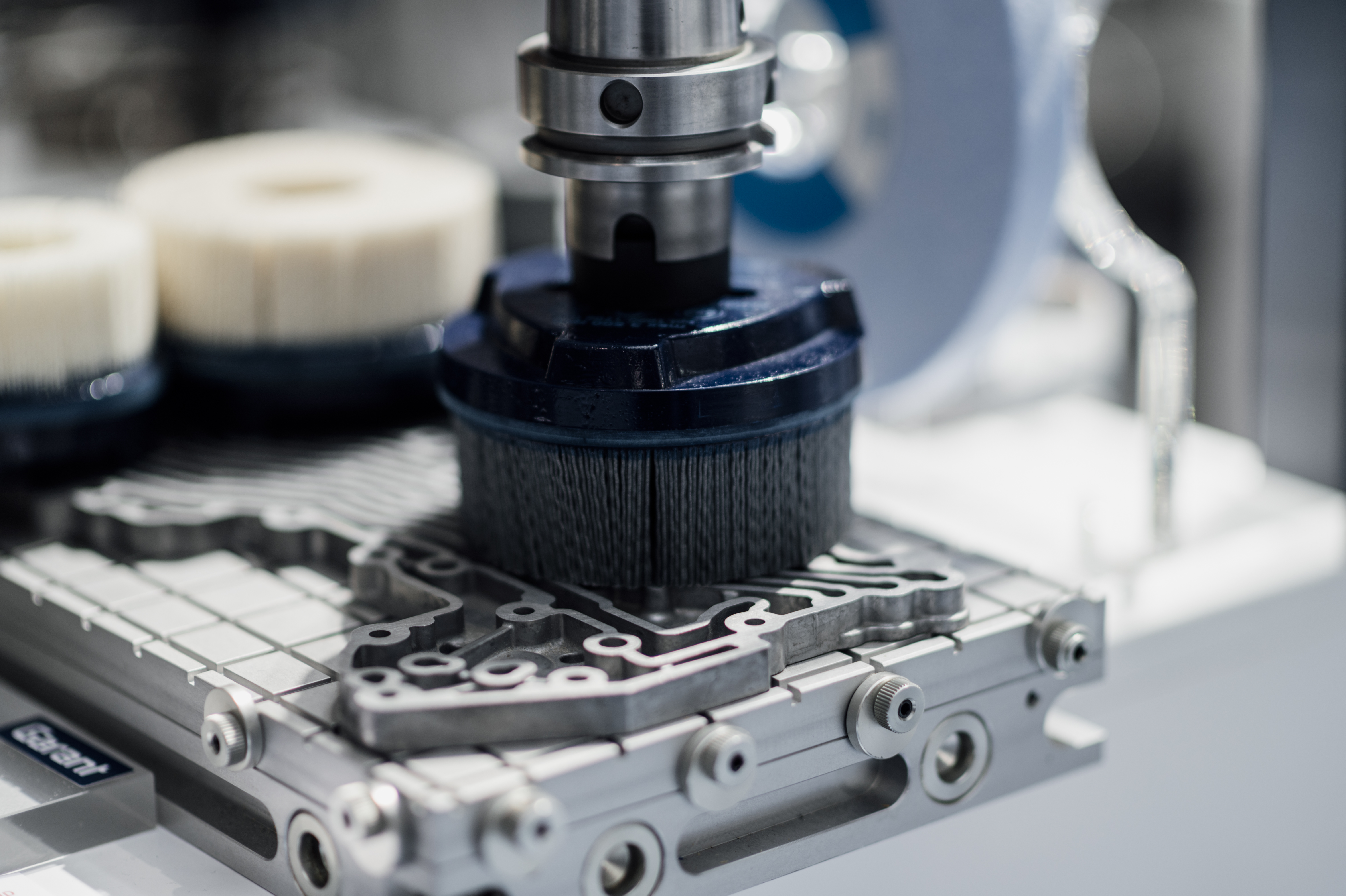
Clean, protect, and package finished diameters to avoid nicks or corrosion. Downstream coating or marking should not compromise the functional outside diameter.
| Question | Reason to resolve it before release |
|---|---|
| Is the part heat treated? | Material condition can change wheel choice, stock allowance, and distortion risk. |
| What edge condition is acceptable? | Functional edges, cosmetic faces, and assembly interfaces can require different deburring instructions. |
Lot Consistency and Acceptance
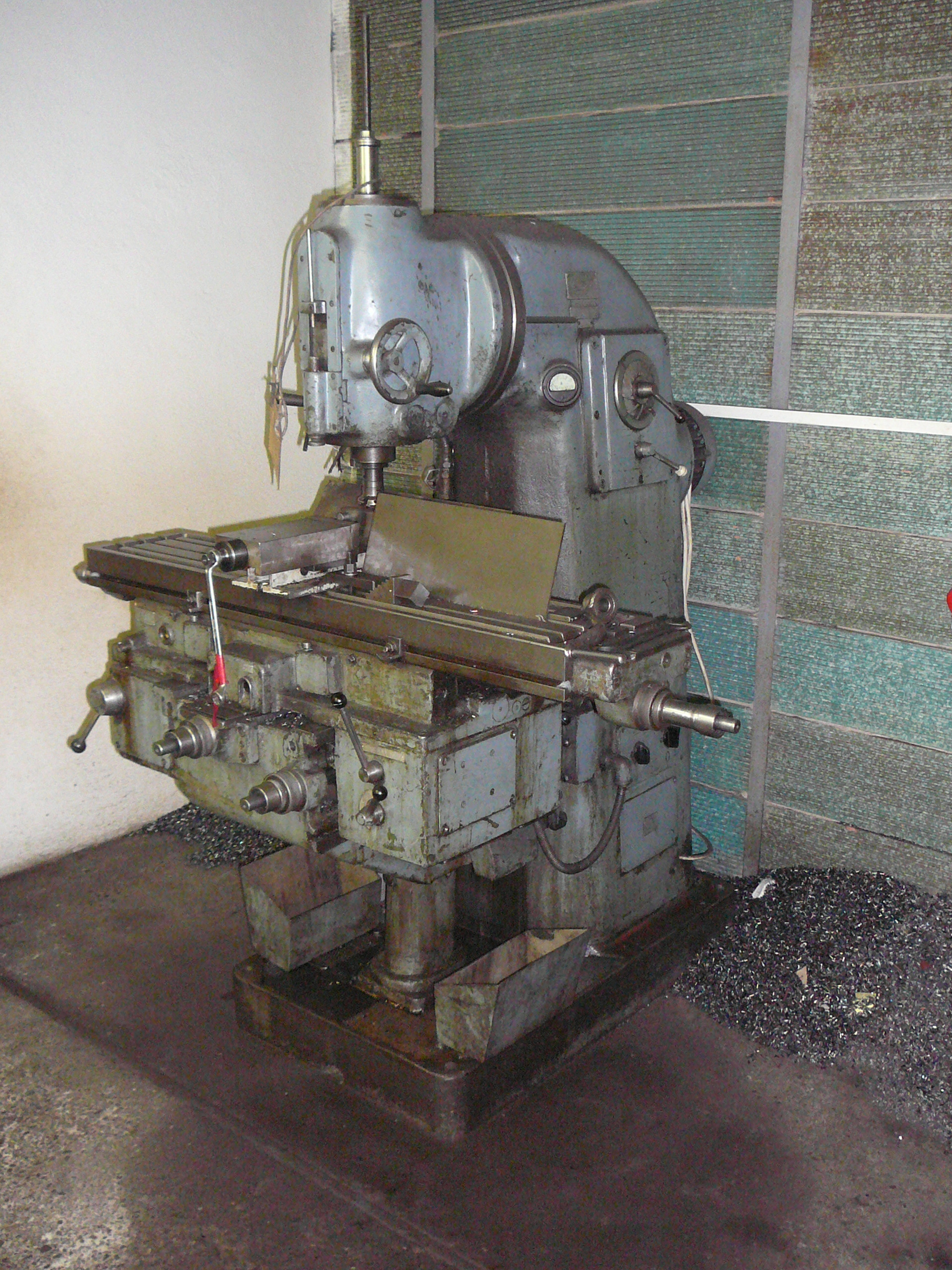
Quality plans can include diameter, roundness, straightness, surface finish, edge condition, and lot-to-lot consistency. Sampling strategy should reflect the function and production quantity of the component.
Inspection-ready RFQ
| Supply | Why it matters |
|---|---|
| Datum scheme and critical geometry | Connects the final surface to the part's functional reference. |
| Mating-part or fit information | Lets the process plan focus on the interface that actually controls performance. |
| Surface and edge expectation | Avoids treating cosmetic and functional requirements as the same thing. |
Key Process Parameters
| Parameter | Typical Value |
|---|---|
| Diameter tolerance | ±0.0025 mm to ±0.0125 mm standard, ±0.001 mm on request |
| Roundness | 0.0005 mm to 0.0015 mm |
| Cylindricity | 0.001 mm to 0.0025 mm over part length |
| Surface finish Ra | 0.1 μm to 0.4 μm (4 to 16 μin) |
| Min diameter | 0.5 mm (micropin applications) |
| Max diameter | Up to 150 mm standard; up to 200 mm with specialty machines |
| Min part length | 1.5 mm to 2 mm short-pin work |
| Max part length | Up to 250 mm in-feed; through-feed parts up to 6 m bar stock |
| Batch range | 50 to 1,000,000+ pieces (production-oriented process) |
| Standard lead time | 1–3 weeks depending on lot size and stock availability |
| Accepted file formats | STEP, IGES, DWG/DXF, PDF drawing; sample parts also accepted for quotation |
| Typical machine | Cincinnati Milacron, Glebar, Royal Master, Koyo, and other through-feed / in-feed centerless grinders with CNC dressers |
Materials We Machine
- Hardened bearing steel – 52100 (SUJ2), AISI 440C, 100Cr6.
- Tool steels – D2, M2, A2, O1, SKD11, S7 (through-hardened to 58–64 HRC).
- Stainless steels – 303, 304, 316, 410, 416, 420, 17-4 PH (condition H900–H1150).
- Carbon and alloy steels – 1018, 1045, 4140, 4340 (hardened or case-hardened).
- Spring steels – 1074, 1095, 301, 302 (tempered to spring temper).
- Carbide preforms – finished to final diameter for cutting tools and wear parts.
- Aluminum and brass – 6061, 7075, C360 brass for nonferrous production runs.
- Ceramics and ferrites – select advanced materials with diamond wheels.
Standard Tolerances & Achievable Precision
Centerless grinding is one of the most accurate and repeatable cylindrical-finishing processes. The numbers below are typical production values, not theoretical limits.
- ±0.0125 mm standard centerless grinding tolerance for general production.
- ±0.005 mm precision centerless grinding on hardened pins, shafts, and rollers.
- ±0.001 mm to ±0.0025 mm ultra-precision on selected bearing and gauge features.
- Roundness 0.0005 mm to 0.001 mm on small-diameter pins.
- Cylindricity 0.001 mm to 0.0025 mm depending on length-to-diameter ratio.
- ISO 2768-m default, ISO 2768-f on tight callouts, with size tolerance per ISO 286 fit class on request.
Surface Finish Options
- As-ground – 0.2 μm to 0.4 μm Ra on hardened steel.
- Fine-grinding / superfinishing – 0.05 μm to 0.1 μm Ra for bearing and sealing surfaces.
- Polished finish – buffing and abrasive belt polishing for decorative or sliding surfaces.
- Passivation – ASTM A967 / A380 on stainless steel pin shafts.
- Black oxide – MIL-DTL-13924D Class 1, 3, or 4 for corrosion resistance and cosmetic appearance.
- Electroless nickel – with post-grinding to maintain tight tolerance.
- Hard chrome – applied to a sub-finish diameter and then finish-ground to size.
- Electroplating – tin, zinc, or decorative finishes on connector pins.
- Laser marking – fine ID / lot marks on end faces away from the ground diameter.
Quality Control & Inspection
Centerless grinding is typically used for high-volume production, so inspection balances accuracy and throughput. A typical QA plan includes:
- Statistical process control (SPC) – diameter, roundness, and finish logged at regular intervals throughout the lot.
- CMM – Zeiss and Hexagon for first-article and capability studies.
- Roundness / form tester – Taylor Hobson Talyrond or Mahr for roundness and cylindricity.
- Surface roughness tester – Mitutoyo SJ-210 or equivalent.
- Pin gages and air gages – high-speed Go/No-Go checks at the machine.
- Optical comparator – for end-face geometry, chamfer, and edge break.
- Hardness tester – Rockwell or Vickers for incoming material and finished surface.
- First-article inspection – documented with FAIR (AS9102) or PPAP where required.
Design Considerations (DFM Tips)
- Use a simple, straight cylindrical form – centerless grinding is most efficient on diameter-only features without shoulders, slots, or cross-holes.
- Specify length-to-diameter ratio ≤ 10:1 – long, slender parts are more difficult to feed and may need a steady rest or work blade support.
- Allow entry / exit geometry – add a small chamfer or lead-in to support smooth feeding and reduce burrs.
- Select stock diameter close to final size – typical pre-grind stock is 0.2 mm to 0.4 mm per side for hardened parts.
- Match material hardness to wheel – hardened steels above 55 HRC usually require CBN; softer steels can use aluminum-oxide wheels.
- Use consistent surface for rest blade – the work rest blade rides on the part; surface must be capable of supporting without damage.
- Avoid center holes, threads, and keyways – the process cannot support these features; they should be machined in a separate operation.
- Consider through-feed vs. in-feed – through-feed for long, simple parts; in-feed for stepped or short features.
- Call out surface finish per feature – a non-functional journal is not the same as a sliding / sealing surface.
- Provide burr and edge-break requirements – define chamfer / radius on each end of the part.
Industries & Applications
- Automotive – valve guides, tappet rollers, transmission pins, injector components.
- Hydraulics & fluid power – piston pins, hydraulic spool guides, pump plungers.
- Electronics & connectors – locating pins, dowel pins, probe pins, connector sleeves.
- Fastener manufacturing – finished shanks, drill blanks, special-thread preforms.
- Tooling – drill blanks, end-mill blanks, reamer blanks, punch pins.
- Aerospace – actuation pins, landing-gear bushings, sensor probes.
- Medical – surgical pins, guide rods, orthopedic implant features.
- Industrial machinery – rollers, guide rods, shafts, and locating pins for jigs and fixtures.
Frequently Asked Questions
When should I choose centerless grinding over cylindrical grinding?
Centerless grinding is best for high-volume, simple cylindrical features without shoulders, especially when the part cannot easily be held between centers. Cylindrical grinding is better for parts with shoulders, internal diameters, tapers, or that need a defined datum.
What is the smallest diameter you can grind?
Approximately 0.5 mm on dedicated micro centerless grinders. Standard machines are most efficient between 1 mm and 50 mm diameter.
Can you grind non-round profiles?
Yes. A CNC-dressed wheel can produce simple non-round profiles, tapers, and contours. Complex profiles are usually better suited to other processes.
What is the stock allowance for centerless grinding?
Typically 0.2–0.4 mm per side. For high-precision features, slightly more allowance is recommended so the wheel can correct stock variation, decarburization, and distortion.
Do you supply the raw material as well?
Yes. We can supply centerless-ground bar stock, or process customer-supplied material. Hardened bearing and tool steel in standard diameters is readily available.
What tolerances can you hold in volume production?
±0.005 mm with surface finish below 0.4 μm Ra is typical for hardened steel pin production runs of 1,000+ pieces, with SPC data to back the capability.
How to Get a Quote
Send us your 3D CAD or 2D drawing, material grade and hardness condition, annual usage or lot size, diameter and tolerance targets, surface finish, and any plating or post-grind finish. For new applications, a sample part or hand sketch with key dimensions is enough to start. We return a DFM note on stock diameter and entry/exit geometry, a quotation per piece or per lot, and a standard lead time for both sample and production quantities.
Process Flow & Manufacturing Sequence
Centerless grinding is a high-throughput, datum-less OD finishing process where the part is supported on a work-rest blade between a grinding wheel and a regulating wheel. The sequence below covers the typical through-feed and in-feed routes used for production cylindrical components.
- Material receipt and lot release – Bar stock, drawn wire, or pre-machined blanks are received with MTC. Diameter, ovality, hardness, and straightness are sampled to confirm they are inside the centerless-grinding stock allowance window.
- Pre-machining (when starting from bar) – Sawing to length, end-facing, chamfering, and any required center drill or end mill feature. Centerless grinding generally assumes the part is ready to be ground on its cylindrical surface.
- Pre-grind cleaning – Parts are washed to remove cutting fluid, oil, and chips that would otherwise contaminate the coolant and load the wheel.
- Through-feed centerless grinding – Long, straight cylindrical parts are fed continuously between the grinding wheel and a slower, rubber-bonded regulating wheel. The regulating wheel is angled 0.5°–3° to advance the part and impart rotation.
- In-feed centerless grinding – Stepped, shouldered, or short cylindrical parts are loaded into a collet or blade nest and plunged against a profiled wheel until the diameter, shoulder, and adjacent land are formed in one station.
- End-feed centerless grinding – Used for tapered parts or parts with a single ground diameter and a defined shoulder; the part advances axially during a timed cycle.
- Wheel dressing – Grinding wheel is dressed with a single-point diamond or rotary dresser to maintain concentricity, expose fresh grit, and (for in-feed) define the shoulder profile.
- Regulating-wheel setup – Regulating wheel angle, speed, and work-rest blade height are set to the part diameter. Work-rest blade is positioned just below the centerline (typically 6–12 mm below).
- Spark-out and size stabilization – Final part revolutions without radial infeed to settle the part on the blade and stabilize the size.
- Through-feed run-out (off-bearing) – The last part leaves the wheel contact and rolls across the work-rest blade; the operator checks the exit temperature and burn-free condition.
- Auto gauging – In-line electronic or air gauges measure the diameter at the exit of the machine; out-of-tolerance parts are diverted by an air ejector.
- Secondary operations (if required) – Honing, superfinishing, light cylindrical OD on a center-type grinder for stepped features, or light deburr on a rotary brush.
- Cleaning and corrosion protection – Aqueous wash, hot-air dry, and VCI bag for ferrous parts.
- Final inspection – Diameter, roundness, cylindricity, and surface finish sampled against AQL; full layout for the first article and at defined intervals per the control plan.
- Marking, packaging, and release – Lot-level laser marking where space allows; bulk-pack into partitioned trays for small parts, individual wrap for long parts.
Material Property Reference
Reference values for materials commonly run through centerless grinding. Machinability rating references AISI 1212 steel at 100%. Higher numbers are easier to cut; centerless grinding uses this loosely as a guide to wheel selection.
| Material | Density (g/cm³) | Tensile Strength (MPa) | Yield Strength (MPa) | Hardness (HB) | Machinability Rating (%) |
|---|---|---|---|---|---|
| Low-carbon steel 1018 (cold drawn) | 7.87 | 470 | 400 | 140 | 78 |
| Medium-carbon steel 1045 (cold drawn) | 7.85 | 585 | 505 | 180 | 60 |
| Alloy steel 4140 (Q&T 28–32 HRC) | 7.85 | 1020 | 900 | 290 | 50 |
| Bearing steel 52100 (through-hardened 60 HRC) | 7.81 | 2240 | 1900 | 650 (HV) | 35 (CBN only) |
| Tool steel D2 (Q&T 60 HRC) | 7.70 | 1860 | 1650 | 620 (HV) | 25 (CBN only) |
| Tool steel M2 (Q&T 62 HRC) | 8.16 | 2150 | 1900 | 650 (HV) | 25 (CBN only) |
| Stainless 304 (annealed) | 8.00 | 620 | 290 | 180 | 45 |
| Stainless 316 (annealed) | 8.00 | 580 | 290 | 170 | 40 |
| Stainless 17-4 PH (H1025) | 7.78 | 1170 | 1070 | 350 | 40 |
| Stainless 440C (HRC 58) | 7.65 | 1750 | 1650 | 580 (HV) | 30 (CBN) |
| Aluminum 6061-T6 | 2.70 | 310 | 276 | 95 | 180 |
| Brass C360 (as-drawn) | 8.50 | 510 | 380 | 130 | 100 |
| Cemented tungsten carbide G20 (ground blank) | 15.0 | 1600 | — | 1600 HV | — (diamond wheel) |
Cost Drivers & Lead Time Factors
Centerless grinding cost and lead time scale strongly with lot size, material hardness, and stock allowance. Because the process is datum-less, fixturing cost is low but in-process gauging and dressing cycles are part of the cycle. The table below summarizes typical timelines for common part families.
| Scenario | Quantity | Typical Lead Time | Primary Cost Drivers |
|---|---|---|---|
| Soft dowel pin, ±0.0125 mm, no HT | 500–5,000 off | 1–2 weeks | Stock cost, in-process gauge, basic packaging |
| Hardened 52100 dowel, ±0.0025 mm | 1,000–10,000 off | 2–3 weeks | Heat-treat queue, CBN wheel, magnetic particle inspection |
| In-feed stepped pin, hardened | 5,000–50,000 off | 3–4 weeks | Wheel profiling, dressing interval, in-line gauging |
| Stainless 304 guide rod, Ra 0.2 μm | 200–2,000 off | 2–3 weeks | Stainless tends to load the wheel, longer dressing, passivation |
| Tungsten carbide blank, ±0.0025 mm | 200–1,000 off | 3–5 weeks | Diamond wheel, low MRR, EDM prep, breakage allowance |
| Aluminum roller, anodized after grind | 1,000–10,000 off | 2–3 weeks | Wheel loading risk, masking for anodize, soft handling |
| High-mix small-batch, 5 SKUs | 50–500 off each | 2–3 weeks | Changeover time, multiple wheel dressers, mixed inspection |
| Aerospace dowel, AS9102 + certs | any | +5–10 days vs standard | First-article, full traceability, FAI report |
Common Defects & Prevention
| Defect | Cause | Prevention |
|---|---|---|
| Barring / chatter marks on the ground surface | Regulating-wheel rubber hardness mismatch, work-rest blade too high or too low, wheel imbalance | Match regulating-wheel durometer to part diameter, set blade 6–12 mm below center, balance and true the grinding wheel |
| Multi-lobe roundness error (tri-lobe, penta-lobe) | Vibration from interrupted cutting, eccentric work-rest blade mounting, draft on the part from prior drawing | Reduce work speed, true the blade, set proper exit angle, use a softer regulating-wheel bond |
| Diameter taper end-to-end | Improper regulating-wheel angle, worn regulating-wheel bearings, change in part entry temperature | Re-set regulating-wheel tilt (typically 0.5°–1.5°), service spindle bearings, stabilize coolant and ambient |
| Wheel loading (glazed finish, burn, size drift) | Soft work material, wrong wheel grade, insufficient coolant, or worn dressing | Use a more open wheel structure, switch to a softer grade, increase coolant pressure, dress more often |
| Spiral lead lines on the part | Regulating-wheel tilt angle too high, or excessive part rotation | Lower regulating-wheel tilt, slow the regulating wheel, use a harder rubber bond |
| Part feeding problem (stall, slow, inconsistent) | Dirty or worn work-rest blade, incorrect blade angle, regulating-wheel surface glazed or contaminated | Clean or replace blade, set blade angle to 0°–30° up, dress the regulating wheel, add vibratory feeder |
| Burrs or feather edges at exit end | Wheel break-down, exit-end burr from prior machining, no chamfer on stock | Add end-chamfering station, redress wheel, install a brush at the exit, switch to a sharper wheel |
| Out-of-tolerance lot (size spread) | Wheel wear between dressings, in-process gauge drift, incoming stock variation | Auto-compensating dresser, frequent gauge calibration, tighter incoming stock control, statistical process control on size |
Comparison With Related Processes
| Aspect | Centerless Grinding | Alternative | When to Choose |
|---|---|---|---|
| Throughput on long, simple cylinders | Highest of any OD finish process; up to 60+ parts/min in production | Cylindrical between-centers: one part per setup | Choose centerless for high-volume pins, rods, and small cylinders without shoulders |
| Concentricity / runout to a datum | No defined datum; only the blade-supported axis | Cylindrical: between-centers or in a chuck | Choose cylindrical when runout to a specific part feature must be controlled |
| Part geometry | Straight cylinders, in-feed stepped features, simple tapers | Swiss turning: complex turned profiles in one setup | Choose centerless when the diameter and finish matter more than profile complexity |
| Hard-material capacity | Effective for through-hardened parts with CBN; surface integrity is good | Hard turning: faster on simple diameters but possible white layer | Choose centerless for fatigue-sensitive dowels and bearing pins in steel |
| Setup and changeover | Quick changeover, but each new diameter needs blade and wheel change | Cylindrical between-centers: longer setup, but flexible on complex parts | Choose centerless when one or two diameters repeat at high volume |
Industry Standards & Certifications
- ISO 9001:2015 – QMS baseline for production grinding shops.
- AS9100D – Aerospace QMS for dowel pins, locating pins, and high-cycle aerospace hardware.
- ISO 13485:2016 – Medical-device QMS for surgical pins, dental blanks, and implant-related dowels.
- IATF 16949 – Automotive QMS for pins, sleeves, and shift-cone components.
- RoHS & REACH – Required for European electrical and consumer-goods supply chains.
- ITAR – Required for defense and military dowel/sleeve parts.
- ISO 2768-1 / ISO 2768-2 – General-tolerance reference for un-toleranced features on the part drawing.
- ASME Y14.5-2018 – GD&T for cylindrical features including runout, cylindricity, and profile.
- ISO 5459 – Datum reference convention used in inspection.
- SAE AS9102 – First-article inspection report format for aerospace pins and rods.
- ASTM A380 / A967 – Passivation reference for stainless-steel pins and rods after grinding.
- AMS 2430 / AMS-QQ-C-320 – Chromium plating reference for ground dowels where wear resistance is needed after grinding.
Packaging, Shipping & Documentation
Centerless-ground parts ship in high volume and are usually bulk-packed in partitioned trays or tubes, with individual wrap reserved for longer parts and ground features. Documentation scales with the customer and the regulatory scope.
- Bulk trays – Partitioned plastic or corrugated trays, with each cavity sized to the diameter to prevent contact damage.
- Tube packaging – Long rods and small-diameter dowels are bundled into spiral-wound tubes with end caps.
- Individual wrap – Anti-corrosion VCI paper or bag for finished ferrous parts that will be stored before next operation.
- Clean-room bagging – Medical or semiconductor dowels sealed in poly bags inside a clean-room environment.
- Outer carton – Double-wall corrugated with reinforced corners; wooden crate for any shipment above 25 kg or 1.2 m length.
- Labeling – Each tray or tube labeled with part number, lot, diameter, and quantity. Outer carton labeled per IATA / IMDG where applicable.
- Shipping options – LTL freight, expedited air, courier, and full container loads for high-volume production.
- Standard documents – Certificate of Conformance (C of C) keyed to part number and revision.
- Material certificate – Mill Test Certificate (MTC) or 3.1 inspection certificate per EN 10204.
- Heat-treat certificate – Furnace run, hardness, and case-depth report when heat treat is in scope.
- First-article inspection – AS9102 FAIR or equivalent dimensional layout for the first production lot.
- SPC / control plan – Xbar-R or short-run SPC charts on diameter, roundness, and Ra; shared with the customer on request.
- Traceability – Lot-level traceability from bar stock heat to finished-part box, retained per the customer contract.
Related Capabilities & Cross-Services
Centerless grinding typically sits between upstream stock prep and downstream inspection or assembly. Combining these services on the same PO reduces part handling and shortens total lead time.
- CNC turning pre-grind – Stock preparation, end-machining, and chamfering of centerless-ready blanks.
- Swiss turning – For complex small-diameter features that need turning before centerless finishing.
- Cylindrical between-centers grinding – For the same part family when there is a need for datum control, shoulders, or internal features.
- Surface grinding – Flat faces and shoulders on the same part family.
- ID grinding – Internal bores on sleeves and bushings in the same lot.
- Superfinishing – Final surface refinement below 0.1 μm Ra for sealing or bearing pins.
- Honing – Cross-hatched micro-finish on hydraulic pins and pump components.
- Lapping – Sub-micron sizing of master pins, gauge pins, and precision dowels.
- Heat treatment – Through-hardening, case-hardening, induction hardening, and tempering coordinated with the grinding sequence.
- Passivation, electropolish, and black oxide – Surface conversion services for stainless, aluminum, and carbon steel ground parts.
- Hard chrome / electroless nickel plating – Plating applied before or after centerless grinding, with masking for precision diameters.
- CMM and optical inspection – Calibrated metrology with full PDF reports.
- Bulk packaging and kitting – Assorted-parts kitting and label service for OEM sub-assemblies.

