
What the Process Does
Turn-mill machining is a hybrid process that combines turning and milling operations within one machine setup. A component can be formed as a rotational profile and then machined with driven or live tools to add flats, cross holes, slots, pockets, threads, or other non-round features. It is especially useful where the part mixes cylindrical and prismatic geometry.
Process Flow
The machining sequence should be planned around the part's functional datums, feature access, material behavior, and the required inspection method. The detailed route is ultimately governed by the actual machine configuration, workholding, tool availability, and production quantity.
|
Process Stage |
Purpose |
|
1. Input review |
Confirm the 3D model, drawing, material, critical dimensions, datums, quantity, and finish requirements. |
|
2. Setup plan |
Select workholding, datum strategy, cutting tools, machining order, and access to all functional features. |
|
3. Machining |
The route normally begins with turning operations that establish the core diameters, faces, and bores. With the part held on the same centerline, live tools or a milling spindle can then produce secondary features such as radial holes, axial holes, flats, keyways, and milled faces. A secondary spindle may be used on certain machines to support additional operations on the reverse side. |
|
4. Verification |
Inspection plans typically check diameters and bores alongside the position of radial holes, flats, slots, and milled faces relative to the turning centerline. Critical datums should connect rotational and prismatic requirements. |
Design Intent
The drawing should make clear which features control the primary rotational datum and which dimensions depend on milled details. Part transfer, live-tool access, collet or chuck engagement, and the order of front- and back-side features should be reviewed early.
|
ENGINEERING INPUT Provide a 3D CAD model, a drawing with critical tolerances and datums, the material grade, requested quantity, surface finish, and any inspection or packaging requirements. |
Part Geometry and Materials
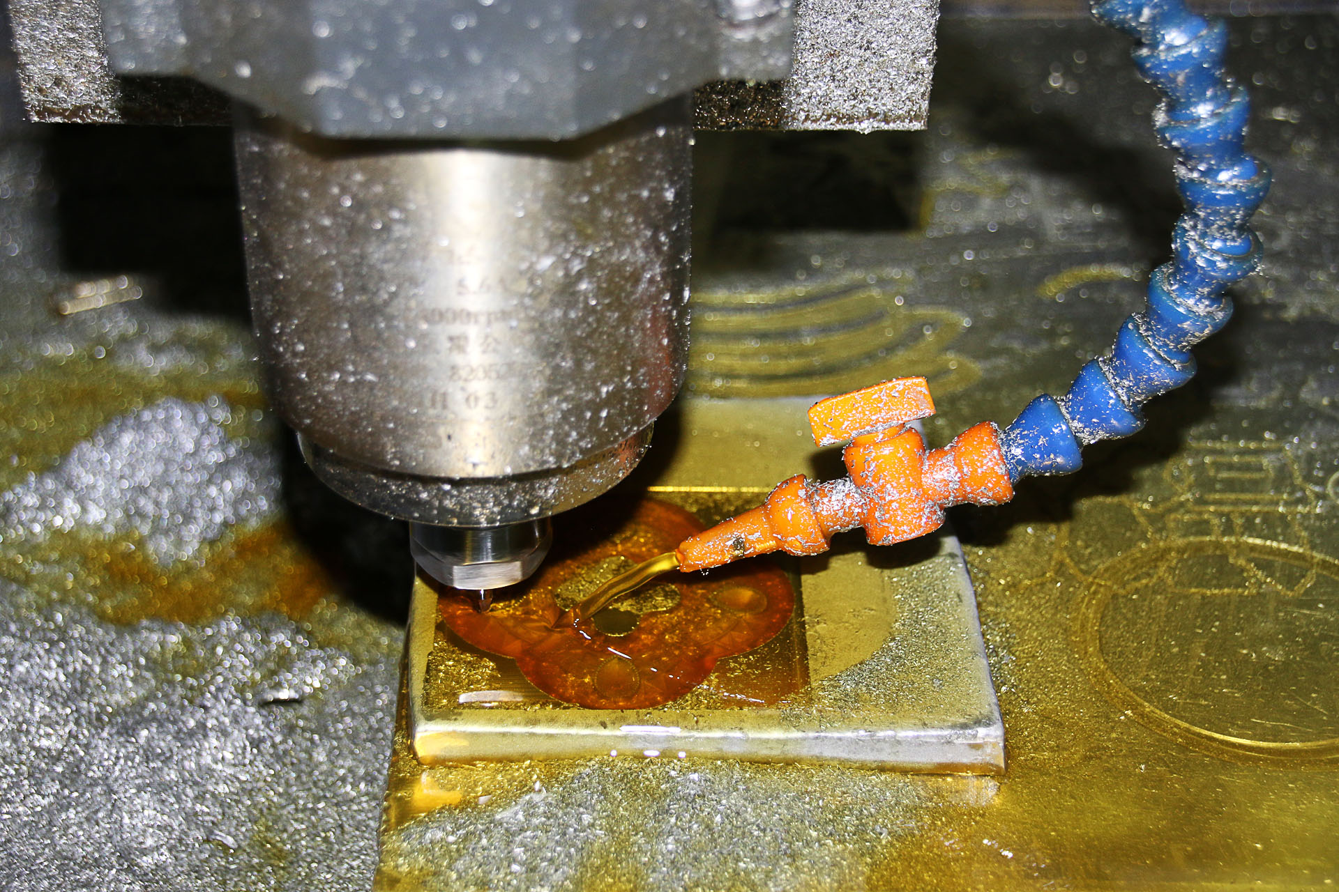
Features and Typical Components
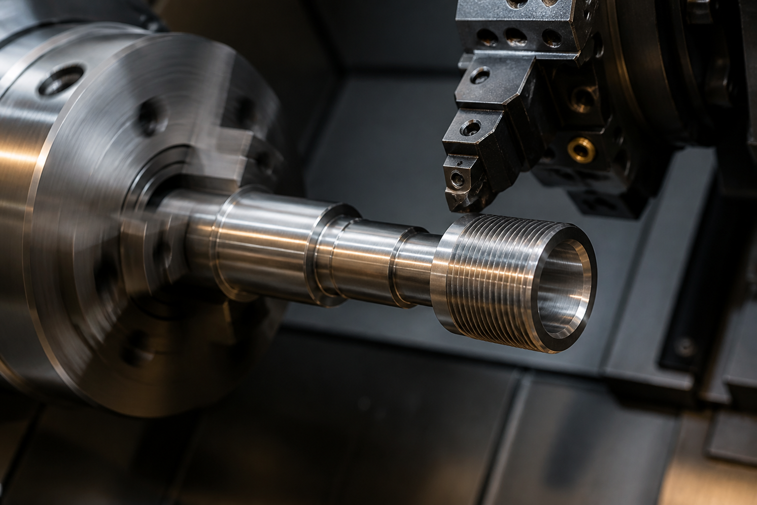
Typical features include turned diameters, threads, grooves, cross-drilled holes, radial patterns, flats, hex or polygon forms, milled slots, keyways, and off-axis locating details.
Typical components Common turn-mill components include complex shafts, hydraulic fittings, valve bodies, medical-device hardware, drive-system parts, adapters, threaded bodies, and parts requiring both a bore and milled interfaces.
Material Selection
The method may be used with aluminum, stainless steel, steel, brass, copper alloys, titanium, and selected engineering plastics. The most suitable material and route depend on rigidity, part geometry, and the intended finish.
|
Material group |
What to consider |
Typical reason for selection |
|
Aluminum |
Machinability, thermal movement, cosmetic finish. |
Lightweight housings, brackets, fixtures, heat-management parts. |
|
Steel & stainless |
Strength, corrosion resistance, heat, chip control. |
Industrial, structural, fluid-system, precision mechanical parts. |
|
Brass, copper & titanium |
Conductivity, corrosion, strength-to-weight, cost. |
Fittings, electrical parts, high-performance or specialized components. |
|
Engineering plastics |
Stiffness, temperature, chemical environment, burr control. |
Insulating, lightweight, prototype, wear or fluid-contact parts. |
| MATERIAL NOTE The material must be selected against functional needs first. Machinability, heat, corrosion, weight, cost, and the desired surface treatment should then be reviewed together. |
Technical Planning and Quality
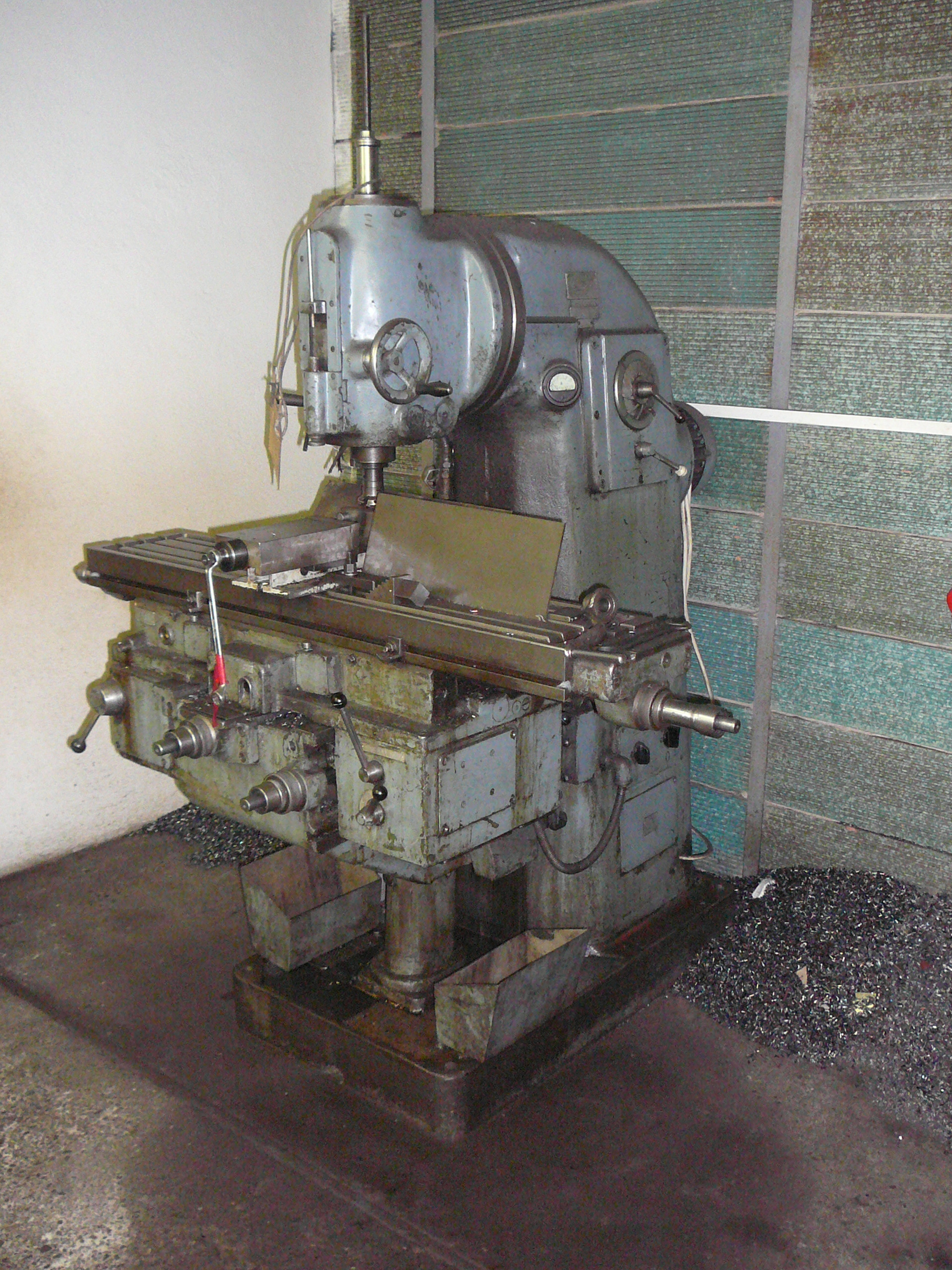
Manufacturing Considerations
The drawing should make clear which features control the primary rotational datum and which dimensions depend on milled details. Part transfer, live-tool access, collet or chuck engagement, and the order of front- and back-side features should be reviewed early.
Quality and Inspection
Inspection plans typically check diameters and bores alongside the position of radial holes, flats, slots, and milled faces relative to the turning centerline. Critical datums should connect rotational and prismatic requirements.
Surface Finish and Part Protection
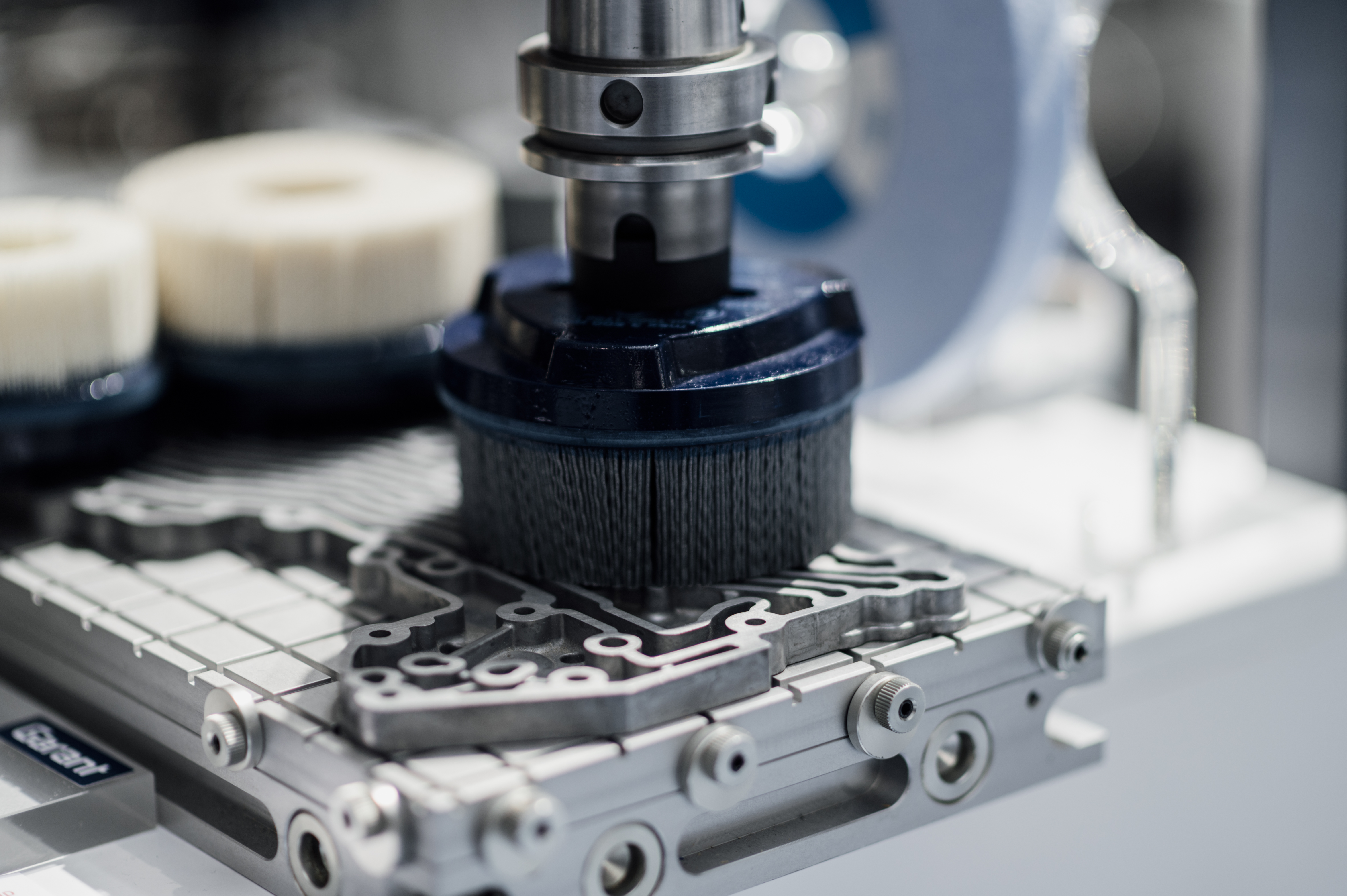
Surface treatment options can include anodizing, black oxide, passivation, plating, blasting, polishing, painting, and laser marking. Cosmetic finish zones should be distinguished from tolerance-critical bearing or sealing surfaces.
Before Production
A manufacturability review should confirm that the tolerance scheme is functional, the specified material is available, the workholding leaves access to critical faces, and the measurement plan can verify all requirements without ambiguity. Where an assembly interface is critical, provide the mating-part information or fit requirement.
|
DRAWING PRACTICE Call out the dimensions that matter to function. Avoid applying an unnecessarily tight general tolerance where only a limited number of features control the fit, motion, sealing, or alignment of the final assembly. |
Advantages and Applications
Why Select This Process
Combining operations can reduce inter-machine handling, preserve datums, and simplify the manufacturing flow for parts that otherwise require a lathe followed by a milling machine.
Application Context
Industrial machinery, fluid systems, robotics, automotive, aerospace, medical equipment, and instrumentation all use components that can benefit from a turn-mill route.
|
Application family |
Where the process adds value |
|
Prototype and product development |
Useful where a functional part, review sample, or process route must be validated before a larger production decision. |
|
Industrial and automation equipment |
Supports durable custom hardware, fixtures, housings, interfaces, shafts, passages, and assembly features. |
|
Precision and regulated equipment |
Supports geometry that must be documented through clear datums, material specifications, inspection requirements, and controlled finishing. |
When to Choose Another Process
Choose turn-mill machining when the part is fundamentally rotational but has a meaningful set of secondary milled or drilled features. Use pure turning for simple round geometry, and use multi-axis milling for predominantly prismatic parts.
|
QUOTE CHECKLIST Include model and drawing files, material grade, order quantity, material certification needs, finishing requirements, critical features, and target delivery date with the RFQ. |
Key Process Parameters
| Parameter | Typical Value |
|---|---|
| Standard linear tolerance | ISO 2768-m, typically ±0.05 mm on machined features |
| Tight tolerance (on request) | ±0.025 mm on critical diameters, bores, and milled features |
| Surface finish, as-machined | Ra 0.8–3.2 µm on turned surfaces; Ra 1.6–3.2 µm on milled surfaces |
| Minimum feature size | M2 thread, Ø0.5 mm end-mill slot, Ø0.8 mm cross-drilled hole |
| Maximum part envelope | Up to Ø65 mm × 300 mm bar capacity; chuck work up to Ø200 mm × 500 mm |
| Number of axes | C-axis turning with X / Y / Z live-tool milling, optional secondary spindle and Y-axis |
| Typical batch size | Prototype single pieces through 10,000-piece production runs |
| Typical lead time | 5–10 working days for prototypes; 10–25 working days for production orders |
| Accepted CAD formats | STEP, IGES, X_T, Parasolid, SolidWorks, CATIA, NX, Fusion 360 |
| Drawing format | PDF with GD&T; native CAD drawings on request |
| Machine platform | Multi-axis mill-turn centres (Doosan / DN Solutions, Mazak, Nakamura, DMG MORI) |
Materials We Machine
- Aluminum alloys — 6061-T6, 7075-T6, 2024-T3, 6082, 5052, 6063, MIC-6 cast plate
- Carbon and alloy steels — 1018, 1045, A36, A572; 4140, 4340 pre-hard and Q&T to HRC 28–32
- Stainless steels — 303, 304 / 304L, 316 / 316L, 321, 410, 17-4PH (H900–H1150), 15-5PH
- Tool and bearing steels — A2, D2, O1, S7; 52100 through-hardened bearing stock
- Brass and copper alloys — C360 brass, C110 copper, C932 bearing bronze, C954 aluminium bronze
- Titanium — Grade 2, Grade 5 (Ti-6Al-4V), Grade 5 ELI
- Engineering plastics — POM (Delrin), PEEK, PTFE, nylon 6 / 66, polycarbonate, UHMW-PE
- Cast and ductile iron — gray iron GG25, ductile iron 60-40-18, ADI grades
Standard Tolerances & Achievable Precision
Default tolerancing follows ISO 2768-m unless otherwise specified on the drawing. Where the part function demands it, tighter limits are held on critical diameters, bores, and milled features relative to the turning datum.
- Standard linear: ±0.05 mm on machined dimensions (ISO 2768-m)
- Tight linear: ±0.025 mm on critical diameters, slots, and hole-to-hole position
- Precision linear: ±0.01 mm on selected features when geometry, material, and batch size allow
- Diametral: ±0.01 mm on bores Ø6–Ø50 mm; ±0.02 mm on diameters above Ø50 mm
- Thread: 6H / 6g metric and 2B / 2A inch on standard taps; thread rolling on selected sizes
- Geometric: position ±0.025 mm, concentricity Ø0.03 mm, perpendicularity 0.03 mm / 100 mm
Surface Finish Options
- As-machined (turning + live-tool milling), typical Ra 0.8–3.2 µm
- Bead blast (glass bead, aluminium oxide) for uniform matte appearance
- Anodizing — Type II (decorative, dyed) and Type III hard anodize (up to 60–80 µm coating)
- Powder coating and wet painting per RAL / Pantone reference
- Electroplating — zinc, zinc-nickel, nickel, tin, chrome (decorative and hard)
- Passivation for stainless steels (ASTM A967 / A380) and black oxide for steels
- Polishing, buffing, and mirror finishing for cosmetic or sealing faces
- Laser marking and engraving for part numbers, logos, and traceability codes
Quality Control & Inspection
Inspection is sized to the drawing and the part's functional role. Typical controls include first-article inspection against the full drawing, in-process checks at defined stages, and a final inspection report on request.
- Coordinate measuring machine (CMM) for dimensional, GD&T, and datum verification
- Surface roughness tester (profilometer) for Ra on turned and milled faces
- Hardness tester (Rockwell, Vickers, Brinell) for heat-treated or surface-hardened parts
- Digital calipers, micrometers, depth gauges, plug and pin gauges for shop-floor checks
- Thread gauges (go / no-go rings and plugs) and optical comparator for thread profile
- First-article inspection (AS9102 / PPAP-style reports available on request)
- In-process checks at defined operation stages and 100% final inspection where required
- Material certification (mill cert / EN 10204 3.1) and traceability on request
Design Considerations (DFM Tips)
- Establish one turning datum and let all secondary features reference it; avoid re-dating between turned and milled surfaces.
- Live-tool slots and pockets should respect the live-tool envelope; deep narrow slots increase cycle time and tool wear.
- Specify thread depth, relief, and end condition clearly — blind threads deeper than 3 × Ø should be reviewed for chip evacuation.
- Allow standard chamfers / edge breaks on all external edges to avoid hand-deburring and protect milled cutters.
- Avoid combining very thin walls with heavy milled features; thin sections deflect under live-tool cutting forces.
- Group cross holes, slots, and flats in a single setup orientation so they can be machined without re-chucking.
- Use standard metric or inch thread sizes and preferred pitches whenever the function allows.
- When the part has back-side features, indicate whether a secondary spindle is required and confirm gripper / clearance.
- Apply generous radii at internal corners (≥ 0.5 × tool Ø) so end mills can enter and exit cleanly.
- Mark cosmetic and functional surfaces separately; the drawing should not require the same finish on both.
Industries & Applications
- Automotive — sensor housings, hydraulic valve bodies, transmission pins, brake components
- Aerospace — hydraulic fittings, instrument mounts, control arm fittings, brackets
- Medical devices — surgical instrument shafts, connector bodies, imaging equipment fittings
- Electronics & semiconductor — RF connector bodies, test fixture parts, vacuum chamber fittings
- Robotics & automation — gear hubs, spline shafts, sensor brackets, end-effector bodies
- Energy — oil & gas valve stems, flow-meter components, wind turbine sensor housings
- Industrial machinery — pump shafts, fastener components, pneumatic fittings
Frequently Asked Questions
When is turn-mill a better fit than a standalone lathe or mill?
When the part mixes rotational and prismatic features and you want all of them produced without a secondary setup. Eliminating the second op removes re-chucking error, reduces handling, and tightens the relationship between the turning and milling datums.
What is the smallest diameter that can be live-tool machined?
Cross holes down to Ø1.0 mm and slots around 0.5 mm width are typically achievable with collet-size bar capacity; smaller features can be evaluated case by case depending on material, depth, and tolerance.
Do you support both metric and inch threads?
Yes. Metric ISO 261, UN / UNC / UNF, BSP, NPT, and custom lead profiles are cut on turn-mill centres. Specify the standard, class, and thread direction on the drawing.
Can you machine parts from bar stock and from billet / forging?
Both. For high-volume runs, bar-fed work reduces material handling and improves consistency. For larger envelopes or higher-grade alloys, we accept billet, forging, or near-net blanks and turn-mill them to print.
What documentation is supplied with the order?
Standard paperwork includes a packing list, inspection summary, and material declaration. On request we supply first-article reports (AS9102 / PPAP-style), material certificates to EN 10204 3.1, certificate of conformance, and signed inspection reports with CMM data.
How is pricing structured for turn-mill work?
Quoting is based on raw-material cost, machine cycle time (set by material, features, and tolerance), tooling, secondary operations such as finishing or inspection, and batch size. Volume breaks and material sourcing are discussed up front so the quote reflects the actual route.
How to Get a Quote
Send the 3D CAD model (STEP preferred) and a 2D drawing with GD&T, the material grade and condition, annual quantity / order size, required surface finish and any post-processing, critical tolerances or inspection needs, and the target delivery date. If a finishing or heat-treatment route is already specified, share those details as well.
Within one working day you receive a written quote including DFM feedback, the proposed machining and inspection route, lead time, and unit price. Prototype quantities are typically scheduled ahead of repeat orders so the transition to production does not restart the clock.
Process Flow & Manufacturing Sequence
A turn-mill part is built in a single setup that combines rotational and prismatic machining on the same machine. The sequence below is the standard route; the actual order of operations is adjusted for the part geometry, the machine configuration, and the lot size.
- Incoming stock preparation — bar stock is cut to length or a forging / blank is rough-cleaned; saw-cut blanks may be faced and centred to make the first chuck load repeatable.
- Load and datum set — the bar or blank is loaded in the main spindle, a sub-spindle, or a powered chuck; a soft-jaw or collet establishes the primary turning datum.
- Rough turning — OD roughing removes the bulk of the stock with indexable tooling; the parting-off cycle is planned but not yet executed.
- Drilling and internal roughing — cross holes, off-centre bores, and back-side features are drilled or rough-bored on the C-axis with live tooling while the spindle is held stationary or indexed.
- Live-tool milling — slots, pockets, flats, key ways, and polygons are machined with driven end mills, drills, and taps mounted in the live-tool turret.
- Finishing turning — critical diameters, shoulders, and seal faces are finish-turned to size with a sharp tool and controlled chip load to keep roundness and surface finish inside the print.
- Thread cutting — internal and external threads are cut with a rigid-tap holder, thread mill, or chasing tool; thread depth and end condition are verified against the drawing.
- Part transfer and back-side machining — when the design calls for features on both ends, the part is picked off by the sub-spindle, regripped, and the remaining operations are performed without a second setup.
- Parting off — the part is separated from the parent stock with a parting tool sized to the diameter and material; final cut parameters are chosen to control burr and flatness on the parting face.
- Deburring, washing, and inspection — chamfers and edge breaks are verified, parts are washed, and the first-article / in-process checks are recorded against the print.
- Secondary operations and shipment — heat treatment, surface finishing, and packaging are scheduled as a downstream flow; lot traceability is preserved through to shipping.
Material Property Reference
| Material | Density (g/cm³) | Tensile Strength (MPa) | Yield Strength (MPa) | Hardness (HB) | Machinability (%) |
|---|---|---|---|---|---|
| Aluminum 6061-T6 | 2.70 | 310 | 276 | 95 | 180 |
| Aluminum 7075-T6 | 2.81 | 572 | 503 | 150 | 160 |
| Brass C360 (free-cutting) | 8.50 | 400 | 140 | 80 | 100 |
| Steel 1018 (cold-drawn) | 7.87 | 440 | 370 | 130 | 70 |
| Steel 4140 pre-hard (HRC 28–32) | 7.85 | 1,020 | 900 | 290 | 55 |
| Stainless 304 / 304L | 8.00 | 580 | 290 | 170 | 45 |
| Stainless 316 / 316L | 8.00 | 580 | 290 | 170 | 40 |
| Stainless 17-4PH (H900) | 7.78 | 1,310 | 1,170 | 380 | 35 |
| Tool steel D2 (annealed) | 7.70 | 760 | 450 | 220 | 30 |
| Titanium Grade 5 (Ti-6Al-4V) | 4.43 | 950 | 880 | 330 | 30 |
| Ductile iron 60-40-18 | 7.10 | 414 | 276 | 150 | 85 |
| PEEK (unfilled) | 1.32 | 100 | 70 | — (Rockwell M99) | N/A (plastic) |
Cost Drivers & Lead Time Factors
The main cost drivers on a turn-mill part are material grade and form (bar, forging, casting), the number of distinct operations, the live-tool envelope and tool count, the batch size, and the inspection and finishing scope. Lead time scales with programming time, raw-stock procurement, fixture build (if any), the heat-treat or plating route, and the inspection plan.
| Scenario | Typical Lead Time | Primary Driver |
|---|---|---|
| Prototype, in-stock material, no finishing | 5–7 working days | Programming, setup, first-article inspection |
| Prototype with custom material and heat-treat | 7–12 working days | Raw-material procurement, outside heat-treat capacity |
| Production run, 50–500 pieces | 10–18 working days | Tool life, cycle time, batch inspection plan |
| Production run, 500–5,000 pieces | 15–25 working days | Bar-feed setup, sub-spindle cycle optimisation, scheduled tool changes |
| Production run, 5,000+ pieces | 20–35 working days | Multi-machine scheduling, in-process SPC, lot traceability |
| Rush / breakdown order (1–20 pieces) | 2–4 working days | Schedule disruption premium; same-day quote turnaround |
| Multi-operation part (drilling + turning + milling + thread mill) | +3–7 working days vs. baseline | Tool count, live-tool indexing, coolant management |
| Part with sub-spindle and back-side features | +2–5 working days vs. baseline | Gripper layout, regrip tolerance, additional tool stations |
Common Defects & Prevention
| Defect | Cause | Prevention |
|---|---|---|
| Built-up edge on tooling | Low cutting speed, wrong tool coating, or insufficient coolant on aluminium, stainless, or titanium | Use polished, coated cutting tools, increase cutting speed, apply high-pressure coolant to the contact zone |
| Live-tool deflection on deep slots | Long tool projection, low rigidity, or excessive radial engagement in stainless and tough alloys | Reduce tool projection, switch to a shorter or larger-diameter cutter, drop radial step-down, take a finish pass with a sharp tool |
| Concentricity drift between turned and milled datums | Excessive milling force on a thin or overhung section, or sub-spindle regrip error | Machine the milling features before parting off where possible; verify regrip clearance and adjust pick-off pressure |
| Cross-hole position error | C-axis index error, tool wear, or part deflection on slender diameters | Verify C-axis calibration, use a steady-rest on slender work, monitor tool wear with regular in-process checks |
| Thread oversize or torn profile | Tap wear, incorrect tap drill size, or synchronised feed drift on rigid tapping | Replace taps on a tool-life schedule, verify tap drill diameter with a pin gauge, and confirm rigid-tap synchronisation at start-up |
| Burr at parting face | Worn insert geometry, excessive feed at break-through, or unsupported part at end of cut | Use a sharp insert, reduce feed at the final 1–2 mm, and add a sub-spindle catch before break-through |
| Surface finish out of spec | Built-up edge, incorrect feed, tool wear, or vibration on long projections | Regrind or replace cutters, reduce feed to the print's Ra target, shorten tool projection, and use a steadier holder |
| Part distortion after cutting | Residual stress in bar stock, heavy milling on thin walls, or excessive gripping force | Stress-relieve material upstream, balance rough and finish passes, lower chuck pressure, and use softer jaws for finish operations |
Comparison With Related Processes
| Aspect | Turn-Mill (this process) | Lathe + secondary VMC | Swiss-Type Turning |
|---|---|---|---|
| Setup count | Single setup, full feature set | Two setups (lathe then mill) | Single setup, sliding headstock |
| Datum relationship | Turning and milling share one datum | Re-chucking introduces stack-up error | Excellent for slender, long parts |
| Part envelope | Up to Ø200 mm chuck, 500 mm length | VMC envelope limits cross-features | Best for Ø0.5–Ø32 mm × 300 mm bar |
| Live-tool capability | C-axis + X/Y/Z + optional Y-axis | Full 3-axis on a separate VMC | Front and back spindles with live tooling |
| Typical lot size sweet spot | 50–5,000 pieces, mixed prototype/production | Low-volume or very large production | 1,000+ pieces in small diameters |
| Best fit | Mixed rotational + prismatic geometry in mid-range sizes | Very large parts, low volumes, or heavy milling on the back side | Long, slender shafts, high volume, tight tolerance |
Industry Standards & Certifications
- ISO 9001:2015 — quality management system baseline for all production
- AS9100D — aerospace quality management system for flight-critical and aerospace assemblies
- ISO 13485:2016 — medical device QMS for instrument and implant components
- IATF 16949 — automotive QMS for serial-production and tier-1 supply
- RoHS and REACH compliance for restricted substances in metallic and plating routes
- ITAR registration for defence-related articles and technical data
- ISO 2768 (general tolerances) and ISO 286 (limits and fits) for default tolerancing
- ASME Y14.5 and ISO 5459 for GD&T symbols, datum reference, and inspection
- EN 10204 3.1 / 3.2 mill certificates available for all supplied raw material
Packaging, Shipping & Documentation
Parts are packed to the surface condition and destination. Precision-machined faces are protected with foam, VCI paper, or individual wrapping, and lots are kept traceable to the mill cert and the production traveller.
- Standard packaging — bulk in sealed PE bags inside corrugated cartons, foam dividers, or layer-pads; individual wrapping for cosmetic or ground surfaces; anti-corrosion VCI paper for steel shipments.
- Custom packaging — customer-specified dunnage, labelled kits, retail-ready trays, vacuum-formed trays, and labelled bags per part number.
- Shipping options — air freight, sea freight (FCL / LCL), courier (DHL, FedEx, UPS, TNT), and EXW / FOB / CIF / DAP incoterms.
- Standard documents — packing list, commercial invoice, certificate of conformance (C of C), material test certificate (MTC) to EN 10204 3.1.
- Inspection documents — first-article inspection report (AS9102 / PPAP), full dimensional report with CMM data, surface-finish and hardness results, material declaration.
- Traceability — lot and heat-number linkage from raw stock through machining, heat-treat, finishing, and shipping; serialisation on request.
Related Capabilities & Cross-Services
Turn-mill parts are usually combined with downstream processes to meet print, finish, and assembly requirements. The most common pairings are listed below.
- Heat treatment — through-hardening, case-hardening, solution treatment and ageing (17-4PH H900–H1150), tempering, and stress relief via approved subcontractors.
- Surface finishing — anodizing Type II / Type III, passivation (ASTM A967), black oxide, electroplating (zinc, zinc-nickel, nickel, tin, chrome), powder coating, wet painting, and bead blasting.
- Grinding — surface, cylindrical, and centreless grinding for tight OD, ID, and flatness features beyond what turning can hold.
- EDM — wire EDM and sinker EDM for slots, small radii, and hardened-material features that cannot be live-tooled.
- 5-axis milling — outsourced 5-axis features when the geometry exceeds the turn-mill live-tool envelope.
- Deep hole drilling and boring — for cross-holes and bores with depth-to-diameter ratios above 10:1 that the turn-mill cannot reach.
- Thread rolling and thread grinding — high-strength external threads on shafts and fasteners.
- Assembly and sub-assembly — pressing, staking, and light mechanical assembly of turn-mill parts into higher-level components.
- Marking and traceability — laser marking, dot-peen, and chemical-etch serial numbers, datums, and customer part codes.
- Reverse engineering and prototype support — part scanning, CAD modelling, and small-batch builds ahead of the production order.

