
What Is 3 Axis CNC Milling
3 Axis CNC Milling is a computer-controlled subtractive manufacturing process that transforms a solid block of material into a finished component. A rotating cutting tool removes material according to a programmed path while the machine operates along three linear directions: X, Y, and Z. The process is commonly used for prototypes and prismatic parts, including plates, brackets, housings, covers, blocks, and mechanical components.
The X-axis controls left-to-right motion, the Y-axis controls front-to-back motion, and the Z-axis controls vertical movement. Together, these movements allow the machine to create accurate holes, pockets, slots, contours, chamfers, and flat surfaces. A digital CAD model or engineering drawing is converted into machine instructions so that the same operations can be repeated consistently.
How the Process Moves from Design to Part
|
01 Design Input 2D drawing, 3D model, material and critical requirements. |
02 CAM Planning Tool selection, workholding, roughing and finishing toolpaths. |
03 CNC Machining Controlled X, Y and Z motion removes material from the stock. |
04 Inspection Dimensions, threads, finish and final part condition are checked. |
A typical workflow begins with the design data and a review of material, critical dimensions, and workholding. CAM software is used to create roughing and finishing paths, simulate material removal, and prepare the program for the machine. The stock is then secured using a vise, clamps, or a dedicated fixture before milling begins.
Common Features and Part Types
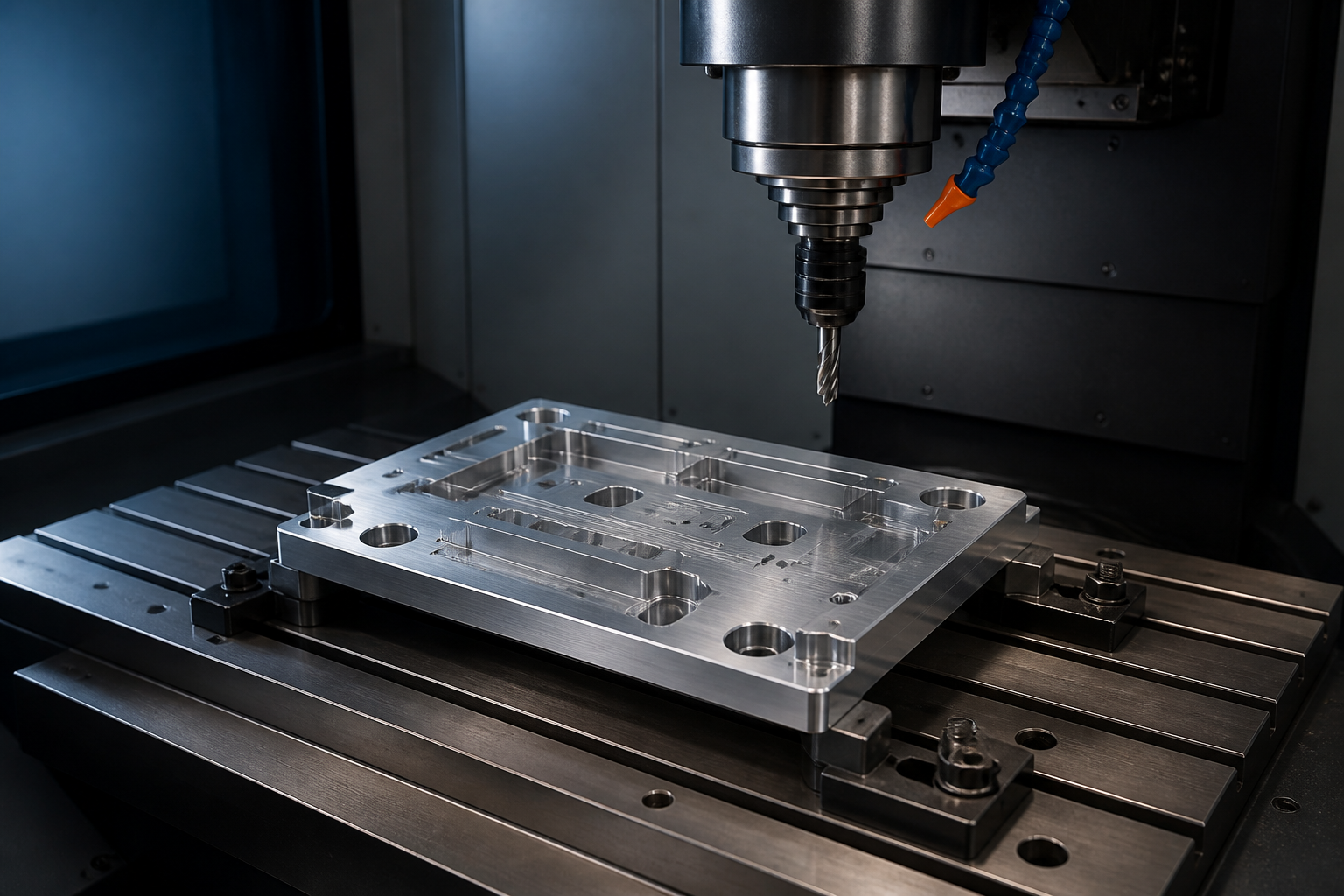
Three-axis milling is most effective when part features are accessible from the top or side faces. It supports a wide range of operations within a single setup, including facing, drilling, tapping, pocketing, profiling, and finishing. This makes it ideal for prismatic parts like housings, brackets, and mold bases. While it cannot machine undercuts or complex freeform surfaces, its combination of efficiency, reliability, and low tooling cost makes it the go-to choice for the majority of everyday production tasks.
|
Area |
What 3-Axis Milling Can Produce |
Typical Part Examples |
|
Surface work |
Facing, contouring, chamfers, and flat reference faces. |
Base plates, covers, panels, mounting faces. |
|
Internal features |
Pockets, cavities, slots, channels, and recessed forms. |
Housings, heat sinks, manifolds, fixture blocks. |
|
Hole features |
Drilled, tapped, counterbored, countersunk, and reamed holes. |
Brackets, adapter plates, electronics enclosures. |
|
Finishing |
Fine passes on selected surfaces; deburring before finishing. |
Prototype parts and repeat production components. |
Why Choose 3 Axis Milling
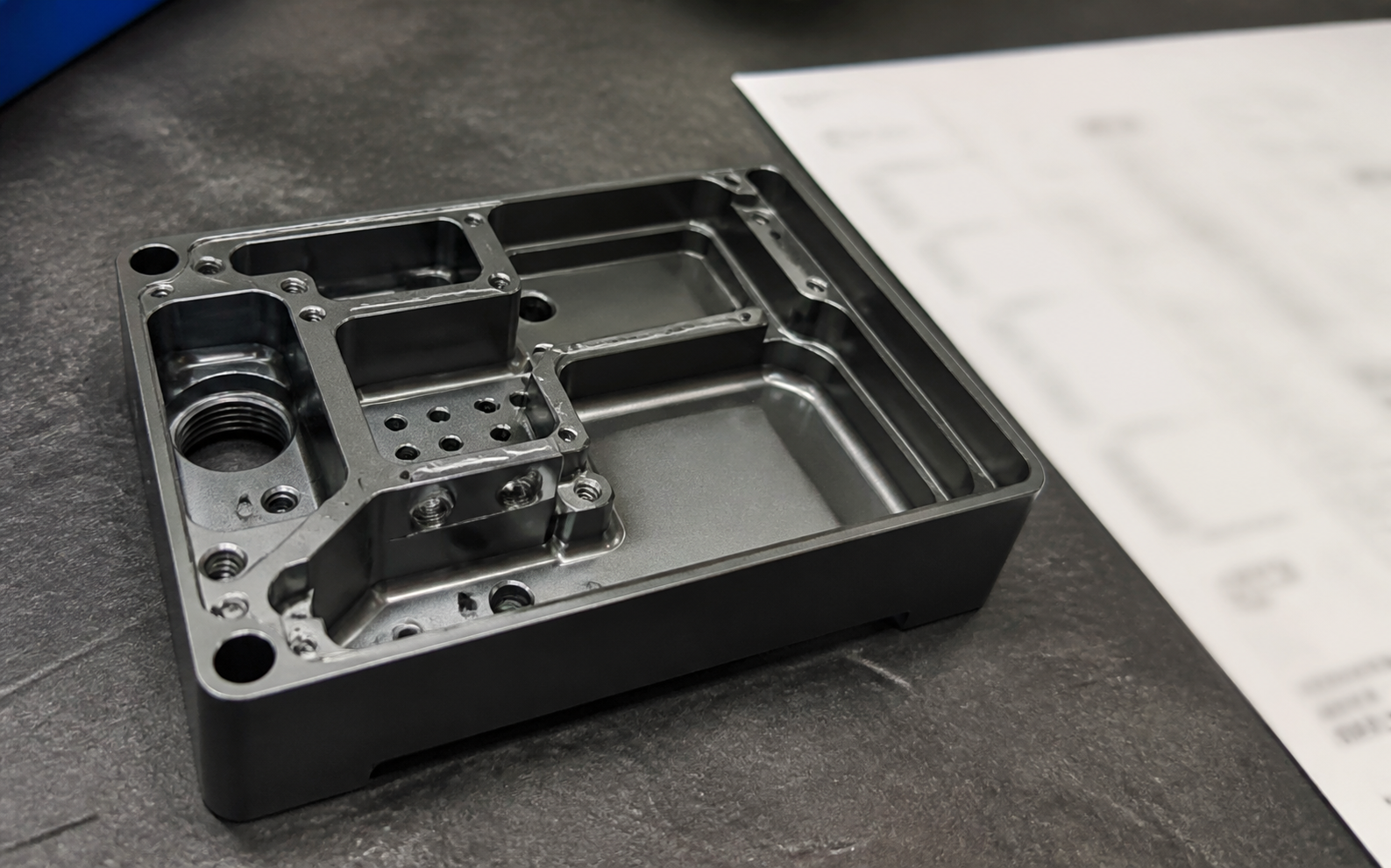
Cost and setup For parts without complex multi-angle geometry, 3-axis machining normally uses simpler fixturing and programming than multi-axis routes. This can make it an efficient choice for standard mechanical designs.
Repeatability Once the workholding and program are established, the same operation sequence can be used for repeat orders, supporting consistent relationships between holes, surfaces, and locating features.
Prototype to production The process can support early prototypes, engineering samples, small-batch components, and scheduled repeat production without requiring molds or casting tools.
Finishing options After machining, parts may receive anodizing, bead blasting, powder coating, painting, plating, polishing, black oxide, passivation, or laser marking depending on the material and end-use requirements.
When 3 Axis Is the Right Choice
3-axis milling is a strong option for flat or block-shaped components with holes, threads, pockets, slots, and accessible profiles. A design with multiple angled surfaces, features around a cylindrical body, or difficult undercuts may require 4-axis or 5-axis machining instead. Choosing the process based on geometry helps control setup count, manufacturing cost, and lead time.
|
DESIGN CHECK Before requesting a quote, provide a 3D CAD file, a drawing that identifies critical dimensions and threads, the material grade, quantity, required surface finish, and any inspection requirements. |
Reference Capability Information
The following information is a factual summary of the Kintec CNC Milling page provided as a reference in this task. It describes the reference website only. It must not be published as your own company information unless your capability, equipment, material range, and dimensions are independently confirmed.
|
Reference Item |
Kintec CNC Milling Page |
|
Listed 3-axis capacity |
Maximum listed 3-axis machining size: 100 x 250 x 250 mm. |
|
Materials listed |
Aluminum, stainless steel, brass, copper, steel, titanium, and plastics. |
|
Equipment mentioned |
3-axis, 4-axis, and 5-axis machining centers; drilling and tapping centers; CNC lathes; conventional machine tools. |
|
Use-case context |
The page discusses CNC milling for parts ranging from prototypes and one-off components to production runs. |
Key Process Parameters
The values below reflect the typical operating envelope of our 3-axis milling cell. Quoted tolerances are achievable on well-supported, prismatic geometry using proper workholding and qualified tooling.
|
Parameter |
Typical Value |
|---|---|
|
Standard linear tolerance |
±0.05 mm (±0.002 in); ±0.025 mm on request; ±0.01 mm for tight-tolerance features |
|
Surface finish (as-machined) |
Ra 1.6 – 3.2 µm typical; Ra 0.8 µm achievable on finishing passes |
|
Minimum feature size |
Down to 0.5 mm slot width and Ø1.0 mm hole with micro tools |
|
Maximum part envelope |
Up to 800 × 500 × 450 mm (3-axis travel, machine dependent) |
|
Batch range |
1 to 5,000+ pieces; prototype through low-volume production |
|
Lead time |
Prototypes 3–5 business days; production 7–15 business days |
|
Accepted CAD formats |
STEP, IGES, X_T, SLDPRT, DXF, DWG (2D drawing) and PDF |
|
Machine platforms |
3-axis VMC, vertical machining center with 12,000–24,000 rpm spindle |
Materials We Machine
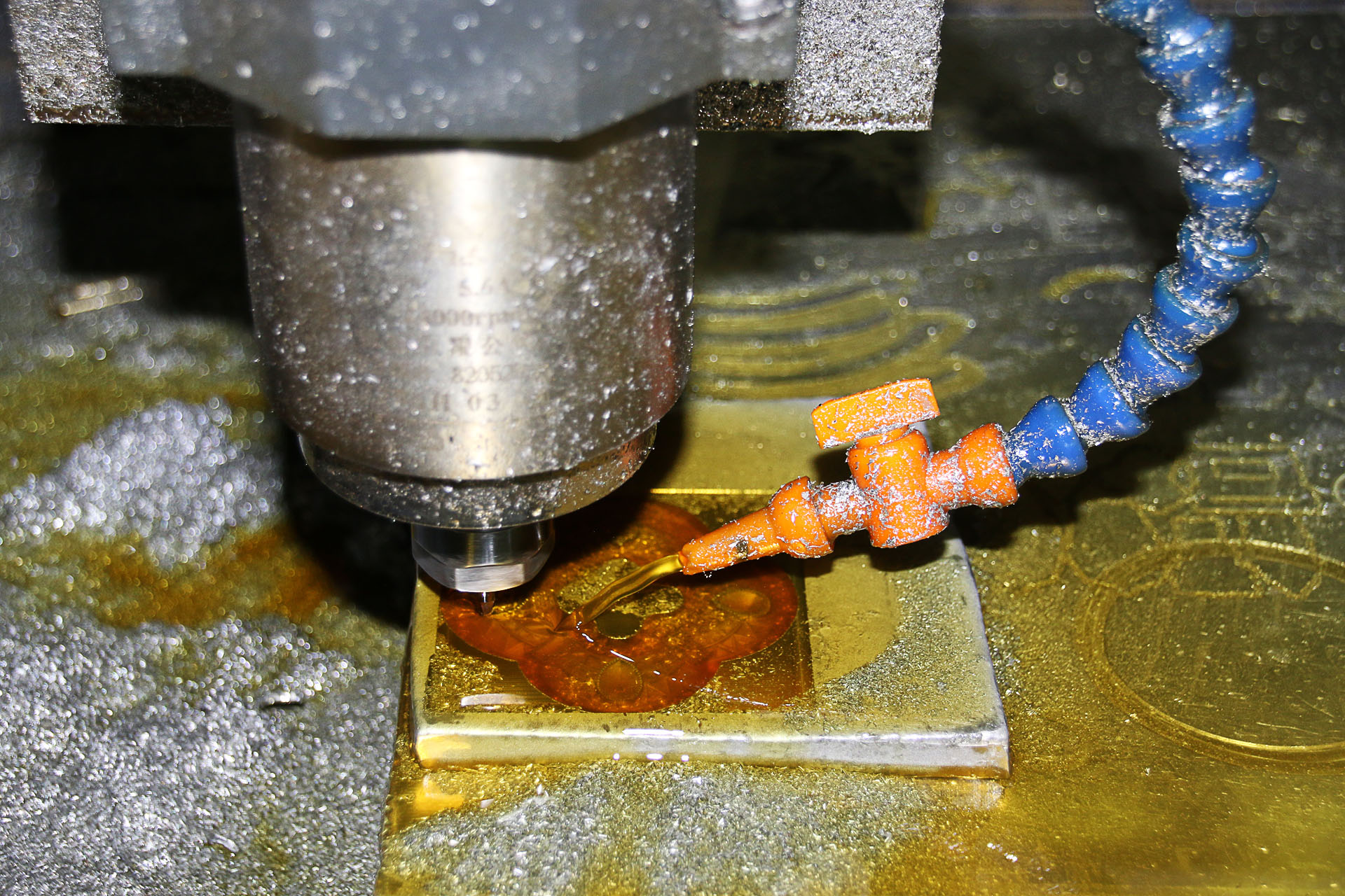
Our 3-axis cell routinely cuts the following families. Stock forms include plate, bar, billet, and forging.
- Aluminum alloys — 6061, 7075, 2024, 5052, 6063, MIC-6 cast tooling plate
- Stainless steel — 304, 304L, 316, 316L, 17-4 PH, 2205 duplex
- Carbon & alloy steel — 1018, 1045, A36, 4140, 4340, tool steel O1 / A2
- Brass & copper — C360 free-machining brass, C110 copper, C954 bronze
- Titanium — Grade 2, Grade 5 (Ti-6Al-4V), Grade 5 ELI
- Engineering plastics — POM (Delrin), PEEK, PTFE, HDPE, nylon, polycarbonate, ABS, Ultem
- Magnesium & specialty — AZ31 magnesium, Inconel 625/718 on request
Standard Tolerances & Achievable Precision
Default tolerance scheme follows ISO 2768-m (medium) unless the drawing specifies otherwise. Tighter callouts are reviewed against feature access, fixturing, and inspection method.
- Standard linear tolerance — ±0.05 mm (±0.002 in) on milled dimensions
- Precision tolerance — ±0.025 mm (±0.001 in) available on critical features
- Tight tolerance — ±0.01 mm (±0.0004 in) by review, dependent on material and geometry
- Hole diameter — Standard drills and reamers; ±0.025 mm achievable
- Flatness / parallelism — 0.03 mm over 100 mm typical on referenced faces
- Position / GD&T — Position, concentricity, and profile tolerancing per ASME Y14.5 or ISO 5459
Surface Finish Options
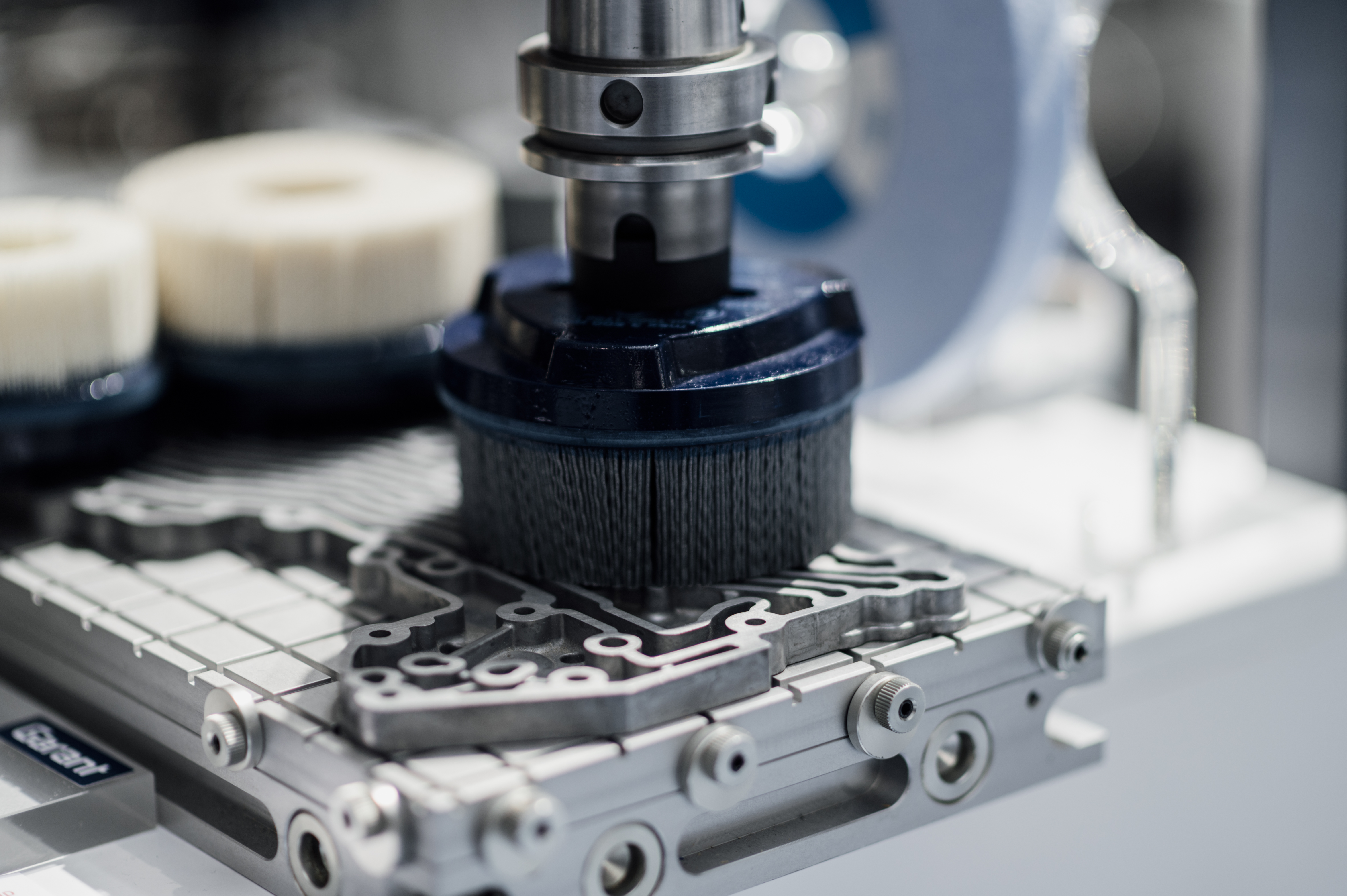
- As-machined — Ra 1.6 – 3.2 µm, standard mill finish
- Bead blast / glass bead / aluminum oxide — uniform matte texture for cosmetic and pre-coat prep
- Anodize Type II — clear or dyed, sulfuric acid, typical 5–25 µm coating
- Hard anodize Type III — PTFE impregnation optional, 25–75 µm, wear-resistant
- Powder coat — polyester, epoxy, or hybrid systems, RAL / Pantone match
- Liquid painting — wet paint, primer + topcoat, custom color
- Electroplating — nickel, tin, zinc, gold, silver (per spec)
- Passivation — ASTM A967 / AMS 2700 for stainless steel
- Black oxide — MIL-DTL-13924, mild corrosion resistance for steel
- Polishing — mechanical or electropolishing to mirror finish
- Laser marking & engraving — logos, part numbers, UID, 2D Data Matrix
Quality Control & Inspection
Every order follows a defined inspection plan. The level of inspection scales with part criticality, drawing callouts, and customer requirements.
- First-article inspection (FAI) — 100 % dimensional report on the first part, AS9102 format on request
- In-process checks — operator measurement at critical operations using calibrated calipers, micrometers, height gauges, and pin gauges
- CMM inspection — Zeiss or equivalent coordinate measuring machine for GD&T, complex datum schemes, and full part coverage
- Surface roughness tester — Mitutoyo SJ-210 or equivalent for Ra verification
- Hardness tester — Rockwell / Vickers for material condition and post-treatment verification
- Final inspection report — dimensional report, material certificate, finish confirmation, and photographic records on request
- Material traceability — mill certificate (MTC) retained for every heat lot
Design Considerations (DFM Tips)
- Internal corner radii — Keep internal corners equal to or larger than the end-mill radius; R ≥ 1.0 mm is preferred for standard tools.
- Standard hole sizes — Specify standard drill sizes; avoid odd-numbered hole diameters that force EDM or boring.
- Wall thickness — Maintain ≥ 1.0 mm in aluminum and ≥ 0.8 mm in plastics; thin walls deflect, vibrate, and complicate fixturing.
- Pocket depth — Avoid pockets deeper than 4× the tool diameter without a step-down or specialty tooling.
- Thread callouts — Use standard metric (M) or unified (UNC / UNF) threads; specify depth of thread, not just hole depth.
- Tolerance discipline — Tighten only functional dimensions. Leave loose tolerances on non-critical features to keep cost down.
- Datum strategy — Establish 3–2–1 datums on the drawing; this determines fixturing and inspection.
- Undercuts & threads — Use standard cutters; if an undercut is non-standard, expect a custom tool charge.
- Surface finish callouts — Specify Ra value with sampling area; clarify whether the finish is before or after coating.
- File format — Provide a clean 3D STEP / IGES plus a 2D drawing with critical callouts.
Industries & Applications
- Aerospace — Interior brackets, structural fittings, prototype airframe components
- Automotive — Prototype engine components, EV battery enclosures, dashboard brackets, prototype gear-housing covers
- Medical & life sciences — Equipment housings, instrument bodies, imaging-system frames, orthotic prototypes
- Industrial equipment — Gearbox covers, mounting plates, manifold blocks, machine guards
- Robotics & automation — End-effector plates, sensor mounts, robot arm links, conveyor components
- Electronics & semiconductor — Chassis, heat sinks, test fixtures, wave-guide components
- Energy — Solar tracker components, wind-turbine prototype fittings, oil & gas sub-assembly blocks
- Consumer & prototyping — Custom enclosures, mechanical prototypes, design-verification units
Frequently Asked Questions
What file formats should I send with my RFQ?
A neutral 3D file (STEP or IGES) plus a 2D PDF drawing with critical dimensions, tolerances, datums, and finish notes is ideal. Native files (SolidWorks, NX, Fusion) are welcome for faster review but not required.
What is the smallest batch size you accept?
Single-piece prototypes and short pilot runs are routine. For quantities above ~50 pieces we typically recommend a dedicated fixture or workholding to keep cycle time consistent.
Can you hold ±0.01 mm on every feature?
Tight tolerances are reviewed case-by-case. ±0.01 mm is achievable on selected features with proper fixturing, temperature control, and CMM verification, but applying it globally drives significant cost and lead time.
Do you supply material, or do I send my own stock?
Both options are supported. Most customers prefer us to source certified material because it simplifies the supply chain and gives us one accountable party for the part.
What finishes can you handle in-house vs. outsourced?
As-machined, bead blast, basic deburring, and light polishing are done in-house. Anodize, plating, powder coat, painting, passivation, and black oxide are routed to qualified partners under our quality system.
Is a digital inspection report included?
Yes. A first-article inspection report is included on every new part, and a final dimensional report is available on request for in-process and production runs.
How to Get a Quote
To generate an accurate quote, please send your 3D CAD model, a 2D drawing (PDF or DWG) with critical tolerances and datums, the material grade, requested quantity, surface finish or coating specification, any inspection or documentation requirements, and your target delivery date. Within one business day, you will receive DFM feedback, a realistic lead time, and a unit / total price. For complex geometry, we can also sign an NDA before file exchange.
Process Flow & Manufacturing Sequence
Every 3-axis milling order follows a defined route from raw stock to packaged part. The exact steps scale with part complexity and batch size, but the order of operations below applies to the majority of prismatic parts we run on this cell.
- Material receiving & verification — incoming bar, plate, billet, or forging is checked against the purchase order and material certificate (MTC). Heat lot, grade, and dimensions are logged for full traceability.
- Stock cutting / sawing — oversized stock is cut to near-net blanks using a horizontal band saw, leaving 1 – 3 mm of machining stock per face for clamping and facing cuts.
- Workholding selection & fixture build — vises, soft jaws, toe-clamps, vacuum plates, or custom fixtures are chosen from the print. For multi-feature parts, a fixture datum is established on the 3-2-1 system called out on the drawing.
- Facing & top-of-stock cleanup — a face mill establishes a clean reference face and a known Z-zero, removing mill scale and saw-induced deformation.
- Rough milling — high material-removal roughing passes using indexable end mills, high-efficiency trochoidal paths, or chip-thinning strategies. Material is removed at maximum allowable chip load for the chosen cutter and material.
- Semi-finish inspection — critical datum features and pilot dimensions are checked mid-cycle using calibrated calipers, micrometers, and height gauges. Adjustments for stock deviation are made before the finishing pass.
- Semi-finish / pre-finish milling — walls and floors are brought to within 0.1 – 0.2 mm of nominal to leave a uniform stock allowance for finishing.
- Drilling & tapping — standard holes, tapped holes, and counterbores are produced with rigid tapping or thread-milling cycles. Hole positions are verified against the print before breaking to the next setup.
- Finishing pass — a finishing pass at reduced radial engagement and feed rate brings walls, floors, and bosses to final dimension, typically achieving Ra 0.8 – 1.6 µm.
- Edge break / chamfer — all sharp edges receive a 0.2 – 0.5 mm chamfer or edge break per drawing callout, applied with a chamfer mill or by hand on critical cosmetic features.
- Deburring & cleaning — hand deburring, tumble finishing, or brush deburr removes residual burrs. Parts are then cleaned in an aqueous wash to remove coolant, chips, and oil.
- Final inspection — 100 % first-article check on the first part, then in-process or sample inspection on the rest of the batch. Surface roughness, hardness, and critical dimensions are verified and recorded.
- Surface treatment (outsourced if applicable) — anodize, plating, powder coat, passivation, or other finishes are routed to qualified partners under our quality system.
- Packaging & shipping — parts are wrapped, bagged, labeled, and packed per customer specification. Documentation is enclosed and the shipment is released.
Material Property Reference
The table below lists typical room-temperature properties for materials commonly cut on our 3-axis cells. Values are industry reference data; actual lot properties are confirmed by the mill certificate (MTC).
|
Material |
Density (g/cm³) |
Tensile Strength (MPa) |
Yield Strength (MPa) |
Hardness (HB) |
Machinability (%) |
|---|---|---|---|---|---|
|
Aluminum 6061-T6 |
2.70 |
310 |
276 |
95 |
180 |
|
Aluminum 7075-T6 |
2.81 |
572 |
503 |
150 |
170 |
|
Stainless 304 |
8.00 |
515 |
205 |
170 |
45 |
|
Stainless 316L |
7.99 |
485 |
170 |
160 |
40 |
|
17-4 PH (H1025) |
7.78 |
1,070 |
1,000 |
330 |
30 |
|
Carbon Steel 1018 |
7.87 |
440 |
370 |
130 |
70 |
|
Alloy Steel 4140 |
7.85 |
655 |
415 |
200 |
55 |
|
Brass C360 |
8.50 |
400 |
140 |
80 |
100 |
|
Copper C110 |
8.94 |
220 |
70 |
45 |
85 |
|
Titanium Grade 5 |
4.43 |
950 |
880 |
340 |
22 |
|
Delrin (POM) |
1.41 |
70 |
65 |
120 (R) |
150 |
|
PEEK |
1.32 |
100 |
90 |
85 (R) |
90 |
Machinability ratings are relative to AISI 1212 steel = 100%. HB values in (R) for plastics denote Rockwell, not Brinell.
Cost Drivers & Lead Time Factors
Quoted unit price and lead time are driven by a small set of well-understood variables. Knowing them up front helps optimize a part for manufacturability and reduce total cost.
What drives cost
- Material — raw stock cost, machinability rating, and the premium for certified grades (e.g. medical, aerospace, nuclear). Exotic alloys such as titanium and Inconel cost more per kilogram and machine more slowly.
- Tolerance — tighter tolerances (below ±0.025 mm) require slower finishing passes, qualified tooling, and CMM verification, all of which add cycle and inspection time.
- Batch size — setup cost is amortized over the batch. Prototypes and short runs carry a higher per-piece setup overhead; production runs of 100+ pieces dilute the overhead.
- Geometry complexity — deep pockets, thin walls, small internal radii, and multi-side features require more setups, more tools, and longer cycle time.
- Surface finish & coating — tight Ra callouts, mirror polish, hard anodize, and specialty coatings add secondary processing time and outside service cost.
- Inspection & documentation — first-article inspection, AS9102 reports, PPAP, CMM programs, and material certification all add engineering and inspection hours.
- Special workholding & tooling — custom fixtures, custom end mills, and specialty cutters carry a one-time charge that is amortized over the run.
What drives lead time
- Material sourcing — common bar sizes in 6061, 7075, 304, 12L14 ship in 2 – 5 days; specialty alloys, large plates, or certified forgings may need 2 – 4 weeks.
- Programming & fixturing — a new part is typically 1 – 3 days of CAM programming and fixture build. Repeat parts run from existing programs.
- CNC cycle time — the actual cutting time per part, which scales with material removal volume, number of setups, and finishing pass count.
- Outsourced processes — anodize, plating, powder coat, and heat-treat are 2 – 7 business days at qualified partners, scheduled into the lead time.
- Inspection & documentation — full FAI, AS9102, PPAP, and CMM programs may add 1 – 3 days depending on part complexity and report scope.
- Shipping — DHL / FedEx international 3 – 5 days; ocean freight 20 – 35 days; air freight 5 – 10 days.
Typical lead times by scenario
|
Scenario |
Prototype (1 – 5 pcs) |
Low-volume (10 – 100 pcs) |
Production (500+ pcs) |
|---|---|---|---|
|
Stock material on hand |
3 – 5 business days |
5 – 7 business days |
7 – 12 business days |
|
Material to be sourced |
5 – 10 business days |
10 – 15 business days |
15 – 25 business days |
|
With outsourced finish (anodize, plating, coating) |
7 – 12 business days |
10 – 18 business days |
18 – 30 business days |
|
With full FAI / AS9102 / PPAP documentation |
+ 2 – 4 business days |
+ 1 – 3 business days |
+ 1 – 2 business days |
Common Defects & Prevention
Most 3-axis milling defects are preventable. The list below covers the failure modes we see most often on prismatic parts, with the root cause and the standard prevention we apply.
|
Defect |
Cause |
Prevention |
|---|---|---|
|
Chatter marks |
Excessive radial engagement, long tool stick-out, insufficient rigidity in workholding |
Reduce radial depth-of-cut, shorten tool stick-out, switch to trochoidal paths, upgrade holder (hydraulic / shrink-fit) |
|
Burr formation |
Dull tooling, exit-side material tear, sharp grain in stainless and aluminum |
Sharp cutter, proper exit ramp, light edge-break pass, tumble or brush deburr as a controlled secondary operation |
|
Wall deflection |
Thin walls and high cutting forces cause the part to spring away from the cutter |
Rough in two sides, light finishing pass on opposite walls, backing plate or fixture rib, low-engagement adaptive clearing |
|
Poor surface finish |
High feed rate, low spindle speed, built-up edge, insufficient coolant |
Reduce feed, increase rpm, switch to coated tool, verify coolant concentration, run a dedicated finish pass |
|
Dimensional drift across batch |
Thermal growth of machine and part, tool wear over long runs, fixture repeatability |
Warm-up cycle, periodic in-process checks, tool-length offsets adjusted on wear, qualified fixture with repeatable stops |
|
Tool breakage |
Chip packing, excessive parameters, wrong tool for material, worn insert |
Match tool to material, use chip-thinning / trochoidal strategies, verify chip evacuation, replace inserts on schedule |
|
Chip evacuation problems |
Deep pockets, stringy chips, insufficient coolant flow, no through-spindle coolant |
Peck-drill cycles, high-pressure coolant, air blast, step-down toolpaths to break chip flow |
|
Thermal distortion |
Heat accumulation on long aluminum or titanium cycles, asymmetric material removal |
Allow thermal stabilization, balance roughing on opposite features, flood coolant with controlled temperature, finish after cool-down |
Comparison With Related Processes
3-axis milling is the most common CNC machining process, but it competes with several adjacent processes. The table below helps select the right process for a given geometry and tolerance.
|
Aspect |
3-Axis Milling (this process) |
4 / 5-Axis Milling |
Turn-Mill / Lathe |
|---|---|---|---|
|
Ideal geometry |
Prismatic parts with features on 1 – 3 faces, plate / block / bracket form |
Multi-face features, radial holes, sculptured surfaces, compound angles |
Cylindrical / rotational parts, shafts, bushings, threaded fittings |
|
Number of setups |
1 – 3 typical |
1 – 2 typical, single-setup for symmetric parts |
1 typical for axisymmetric parts |
|
Tightest tolerance |
±0.01 mm by review |
±0.01 mm on critical features; tighter profile on freeform surfaces |
±0.01 mm on diameter with fine finishing |
|
Cost vs. this process |
Baseline (lowest cost for prismatic parts) |
+ 20 – 50 % programming, longer cycle, higher hourly rate |
Lower cost for axisymmetric parts, higher if extensive milling is required |
|
When to choose |
Flat plates, brackets, housings, covers; cost-sensitive parts with prismatic features |
Multi-face parts, compound angles, sculpted surfaces, complex one-setup parts |
Shaft- or sleeve-type parts, threaded components, large-diameter round parts |
Industry Standards & Certifications
Our quality system and machining practice are aligned with the standards below. Specific certifications are referenced in the project scope when customer requirements demand them.
- ISO 9001:2015 — quality management system baseline; the foundation for all our manufacturing processes.
- AS9100D / AS9102 — aerospace quality management; first-article inspection report format for aerospace parts.
- ISO 13485:2016 — medical device quality management, applicable to medical and life-sciences parts.
- IATF 16949 — automotive quality management, aligned to PPAP and APQP documentation.
- ISO 2768 — general tolerances for linear and angular dimensions (medium / fine / very fine classes).
- ASME Y14.5-2018 — geometric dimensioning and tolerancing (GD&T) standard, including datum scheme and feature control frames.
- ISO 5459 — datums and datum systems for geometric specification.
- ISO 1101 — geometrical product specifications (GPS), tolerancing of form, orientation, location, and run-out.
- ASTM A967 / AMS 2700 — passivation of stainless steel parts.
- MIL-DTL-13924 — black oxide coating for steel.
- ASTM B851 / MIL-A-8625 — anodize Type II / Type III on aluminum.
- RoHS / REACH — restricted substance compliance for European market access.
- Conflict Minerals (CMRT / RMI) — reporting for tin, tantalum, tungsten, and gold sourcing.
- ITAR / EAR — controlled technical data and export compliance for defense-related parts where applicable.
Packaging, Shipping & Documentation
Parts are packed to protect machined surfaces, threads, and precision features during transit. Documentation is enclosed per customer requirement and retained in our quality system.
Standard packaging
- VCI (volatile corrosion inhibitor) bag — applied to all steel and iron parts to prevent oxidation during shipping and storage.
- Individual foam wrap or compartmentalized trays — protects machined surfaces from contact damage; multi-cavity trays for small parts.
- Sealed poly bag — keeps parts clean and dry for medical and optical applications.
- Cardboard cartons with partition / divider — for small and medium parts in production runs.
- Custom plywood / wood crating — for large, heavy, or precision parts above 25 kg, with foam lining and edge protection.
- ESD-safe packaging — for parts that will be integrated into electronics or semiconductor equipment.
- Labeling — part number, lot / batch, quantity, material, and customer reference number on every outer and inner package.
Shipping options
- DHL / FedEx / UPS — international express, 3 – 5 business days door-to-door, full tracking, and customs handling.
- Air freight — 5 – 10 business days for heavier shipments; consolidation available for cost-sensitive cargo.
- Ocean freight (FCL / LCL) — 20 – 35 days for non-urgent production runs; full-container or shared container.
- Customer-arranged courier — parts can be released to a customer-provided account on request.
- EXW, FOB, CIF, DAP — Incoterms supported per customer preference.
Standard documentation
- Certificate of Conformance (C of C) — confirms parts were manufactured to the drawing and meet specified requirements.
- Mill Test Certificate (MTC) — original material certificate from the mill, retained for every heat lot.
- First-article inspection report (FAI / AS9102) — 100 % dimensional report on the first part of a run.
- Dimensional inspection report — recorded measurements of critical features across the batch.
- Surface finish report — Ra measurements where called out on the drawing.
- Certificate of Origin (CoO) — for customs clearance, where applicable.
- Commercial invoice & packing list — standard shipping documentation.
- PPAP / APQP package — for automotive customers, including control plan, PFMEA, and capability data.
Related Capabilities & Cross-Services
3-axis milling is the workhorse of our cell, but it is rarely the only operation a part needs. We coordinate downstream services so the customer sees a single accountable supplier, not a list of subcontractors.
- Post-machining finishing — bead blast, tumble, hand deburr, light polishing, edge-break, and cosmetic buffing in-house.
- Anodizing & plating — Type II / Type III anodize, electroless nickel, zinc, tin, gold, and silver plating through qualified partners.
- Powder coat & wet painting — polyester, epoxy, hybrid systems, RAL / Pantone color matching, primer + topcoat, and clear coat.
- Heat treatment — through-hardening, case hardening, tempering, solution treatment, and aging (e.g. 17-4 PH H900 / H1025 / H1075).
- Light assembly & kitting — fastener installation, insert pressing, sub-assembly, and kit packaging.
- Laser marking & engraving — part numbers, logos, UID, 2D Data Matrix, and traceability codes.
- Design for manufacturing (DFM) review — feedback on tolerances, features, and material selection before cutting chips.
- Reverse engineering — point-cloud-to-CAD reconstruction for legacy parts and tooling.
- CMM inspection & 3D scanning — full GD&T verification, CAD-comparison, and reverse-engineering scans.
- Subcontracted services coordination — single point of contact for heat-treat, plating, anodize, and coating partners.
"

